M. To create a group from a selection
To create a new group using a selection of model objects, use the following procedure.
Group names are a means for easily identifying a collection of entities like Beams, Plates or Solids using a single moniker. By grouping these entities, we need to assign attributes such as member properties and material constants just to the group, a simple process, compared to the task of assigning them to the individual members.
The file EX. US-1 Plane Frame with Steel Design is used to demonstrate this feature.
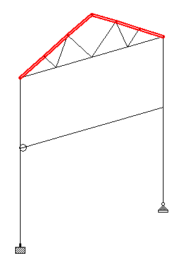
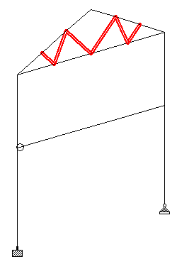
Consider the members which form the truss as being in one of three groups: Top Chords, Bottom Chords, and Web Members.
- Select the top chord members: With the model open, use the Beam Cursor tool to select the members forming the top chords (i.e., members 8 through 13).
-
Either:
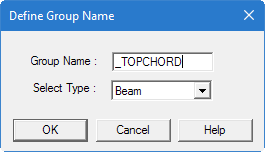
If you have not previously defined any groups, the Define Group Name dialog opens. Otherwise, the Create Group dialog opens (skip to step 4).
-
Specify the group details:
- Type a name in the Group Name field. A group name such as _TOPCHORD can be used for this example.
-
Select the object type from the
Select Type drop-down list.
Groups can consist of nodes, beams, plates, solids, and a general category called geometry. Geometry can be used to associated objects of mixed types.
Select Beam for the top chords example. - Click OK.
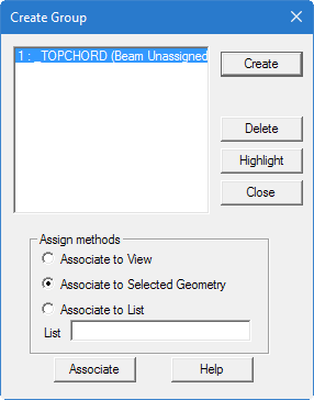
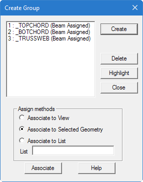
The Create Group dialog opens. At this point, you have created a group name but it does not yet contain any objects.
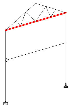
- Select Associate to Selected Geometry and then click Associate. The selected members are added to the group.
- Select other model objects. For the example file, the members forming the bottom chord (members 20, 21, 22, and 23).
- Associated these members with a new group:
- Repeat steps 5 and 6 to create additional groups as needed. For the example file US-1 Plane Frame with Steel Design.std, you can select the truss web members (members 14, 15, 16, 17, 18, and 19) and add them to a group named _TRUSSWEB
- Click Close in the Create Group dialog.