AD.2005.1.5 Property Calculator for User Table General Sections
The user table section type called General has been enhanced in the following manner:
- The shape of the section can be defined in terms of coordinates of the corner points of its cross section outline
- A section property calculator built into that dialog box enables the values to be calculated instantaneously. Any values the user wishes to override can be changed by typing over them.
- Points can be defined at which stresses are to be reported in the Beam-Stresses page of the post-processing mode.
Description
Select , and choose the length unit in which to specify the dimensions of the cross section. Let us choose inches for this exercise.
Next, select . In the Create User Provided Table dialog box, click on New Table.

Select General for the Select Section Type. Click on OK.
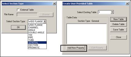
The table number will appear as 1. Click on Add New Property. The following dialog box will appear.

Let us say that we would like to define a cross section as shown below.
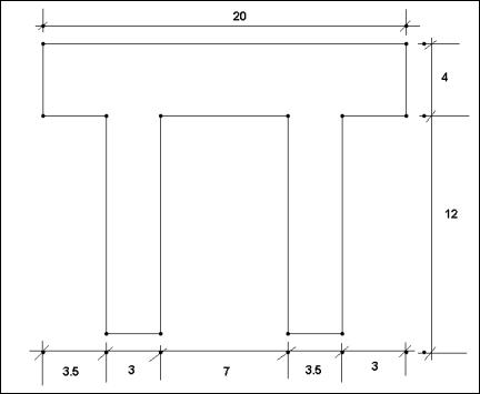
Assuming the top left corner of the cross section to be (0,0) for (Y,Z), , Z being along left-right and Y along top-bottom, specify the data as shown in the next figure. The sequence of steps is circled in the next figure. Once the points are specified, click on Compute Section Properties and observe the values being computed and filled in the relevant boxes (step 4 in the next diagram)

Steps
- Select Define Profile Polygon
- Type TWOLEGGEDTEE in the Section Name field.
- Type the vertex coordinates in the table.
- Click Compute Section Properties.
You will observe that when we clicked on Compute Section Properties, the Y and Z coordinates of the corner points that we typed earlier will be replaced by values that are measured from the center of gravity of the section.
If you wish to specify the locations on the cross section where stresses are desired, they must be provided too. Note that the coordinate locations for that box should be based not on the arbitrary datum point we started out with initially, but on the basis of the center of gravity of the section.
 These are points where stress reports are desired in the Beam | Stresses page in the post-processing mode. The coordinates of these points are measured from the CG of the section and not from an arbitrary point.
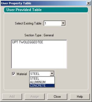
Once the section is defined, it may be assigned from the General-Properties page in the conventional way. Some of those steps are shown in the next 2 figures.

For the case of the example above, the following command syntax will appear in the STAAD input file.
START USER TABLE
TABLE 1
UNIT INCHES KIP
GENERAL
TWOLEGGEDTEE
152 16 20 0 3395.93 4520.67 638.828 452.067 586.57 83.3308 -
46.3944 625.529 625.529 95637 .5 0
PROFILE POINTS
0 0 0 -4 3.5 -4 3.5 -16 6.5 -16 6.5 -4 13.5 -4 13.5 -16 16.5 -16 16.5 -4 20 -4 20 0
STRESS LOCATIONS
-10 5.78947 10 5.78947 -6.5 -10.2105 6.5 10.2105
END