M. To create a general section
To create a user provided table section with a general profile, use the following steps.
You may want to change the input dimensions prior to creating user provided table sections. Select to do so.
-
On the
Specification ribbon tab, select the
tool in the
Beam Profiles group.

If no User Defined Table exists, you will be prompted to create one.
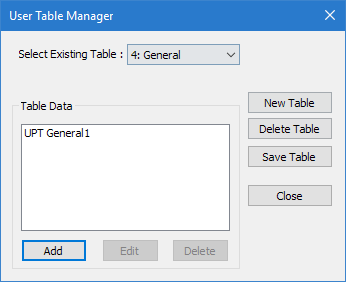
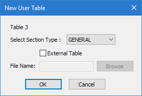
The User Table Manager dialog opens. - Click New Table. The New User Table dialog opens.
- In the Select Section Type list, select GENERAL and then click OK. The dialog closes and the Select Existing Table list in the User Table Manager dialog now has at least one entry.
-
Click
Add.
The General dialog opens.
- Type a Section Name.
-
Either:
Type the section properties if these are available in the corresponding fields
or
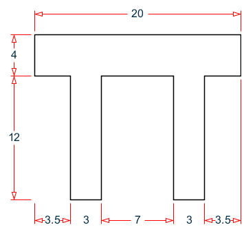
Set the Define Profile Polygon and enter in Z,Y coordinates of the section apexes.
The following is an example cross section, with corresponding Z,Y coordinates which can be copy/pasted directly into the table.
-
The section properties can be calculated based on coordinates or directly
entered.
If… Then… you want to manually specify the section properties type the values in the corresponding section property fields you entered in section corner coordinates click Compute Section Properties The section properties are calculated and the Ax, Ay, Az, Ix, Iy, Iz, Py, Pz, DEE, HSS, SY, SZ, B, and D fields are updated.
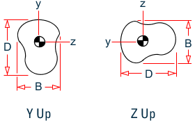
Setting Description AX Cross section area D Largest dimension parallel to the local Y axis (overall section depth along Y). TD Thickness associated with section element parallel to Y axis (taken to be the web). To be used to check depth/thickness ratio of the web. B Largest dimension parallel to the local Z axis (overall section width along Z). TB Thickness associated with section element parallel to Z axis (taken to be the flanges). To be used to check width/thickness ratio of the flanges. IZ Moment of inertia about local z axis IY Moment of inertia about local y axis IX Torsional constant SZ Section modulus about local z axis (about the local y-axis for Z up) SY Section modulus about local y axis (about the local z axis for Z up) AY Shear area in local y-axis (about the local z axis for Z up) AZ Shear area in local z axis (about the local y-axis for Z up) PZ Plastic modulus about local z axis (about the local y-axis for Z up) PY Plastic modulus about local y axis (about the local z axis for Z up) HSS Warping constant for lateral torsional buckling calculations DEE Depth of web between the flanges. For rolled sections, distance between fillets should be provided - (Optional) If you want to have section stress calculated, enter Y,Z coordinates in the Stress locations in local coordinates
- Click OK. The section is added to the list in the Create User Property Table dialog.
- (Optional) Repeat steps 4 through 9 to add more General sections.
- Click Close.

The section can now be added for use in the Properties - Whole Structure dialog by selecting it in the User Property Table dialog.
Example
The example given in step 6 creates the following lines in a STAAD input file:
…
TABLE 1
UNIT INCHES KIP
GENERAL
General1
152 16 0 20 0 3395.93 4520.67 638.828 332.591 452.067 83.3308 -
46.3944 760 625.529 95637.5 16
PROFILE_POINTS
-10 5.78947 -10 1.78947 -6.5 1.78947 -6.5 -10.2105 -3.5 -10.2105 -3.5 1.78947 3.5 1.78947 -
 3.5 -10.2105 6.5 -10.2105 6.5 1.78947 10 1.78947 10 5.78947
STRESS_LOCATIONS
-10 5.78947 10 5.78947 -6.5 -10.2105 6.5 -10.2105
END
…