TR.20.1 Assigning Properties from Steel Tables
The following commands are used for specifying section properties from built-in steel table(s). The section type specification is followed by additional specifications as needed.
General Format
member-list TABLE type-spec table-name additional-spec
Where:
| Parameter | Description | |||||||||||||||||||||||||||||||||||||||
|---|---|---|---|---|---|---|---|---|---|---|---|---|---|---|---|---|---|---|---|---|---|---|---|---|---|---|---|---|---|---|---|---|---|---|---|---|---|---|---|---|
| member-list | A list of member numbers. | |||||||||||||||||||||||||||||||||||||||
| type-spec |
= { ST | RA | D | LD | SD | T | CM | TC | BC | TB | FR }
|
|||||||||||||||||||||||||||||||||||||||
| table-name | Table section name like W8X18, C15X33 etc.
The documentation on steel design per individual country codes contains information regarding their steel section specification also. For details on specifying sections from the American steel tables, refer to D1.A.4 Built-in Steel Section Library. |
|||||||||||||||||||||||||||||||||||||||
| additional-spec |
= * {SP f1 | WP f2 | TH f3 | WT f4 | DT f5 | OD f6 | ID f7 | CT f8 | FC f9 | CW f10 | CD f11 | BW f12 | BT f13 }
|


Refer to G.6.2 Built-In Steel Section Libraries for more information.
Parametric Pipe and Tube Sections
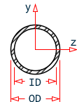
In lieu of specifying a table shape, you can specify pipe and tube sections parametrically. Only the standard (ST) single sections are used for pipes and tubes for table sections. So the input format for a pipe section is:
member-list TABLE ST PIPE OD f6 ID f7
The input format for a tube section is:
member-list TABLE ST TUBE DT f5 WT f4 TH f3

US Steel Joist Sections
Several tables of US steel joists and joist girders are available for use. Member properties can be assigned by specifying a joist designation contained in tables supplied with the program. The following joists and joist girder types have been implemented:
- Open web steel joists – K series and KCS joists
- Longspan steel joists – LH series
- Deep Longspan steel joists – DLH series
- Joist Girders – G series
The format for specifying steel joists is
MEMBER PROPERTIES SJIJOIST
member-list TABLE ST section-name-in-table
The STAAD.Pro joists database includes the weight per length of the joists. Thus, the weight of the joist is automatically considered for selfweight computations in the model.
The designation for most joists (K, KCS, LH, and DLH series) are similar to those given in the SJI publication (e.g., 16K2, 22KCS4, 24LH05, 60DLH13).
The designation for the G series Joist Girders is as shown in the Steel Joist Institute publication. STAAD.Pro incorporates the span length also in the name, as shown in the next figure.

STAAD.Pro nomenclature for SJI joist girders
Examples
UNIT  …
MEMBER PROPERTIES
1  TO  5  TABLE  ST  W8X31
9  10  TABLE  LD  L40304  SP  0.25
12  TO  15  PRISMATIC  AX  10.0  IZ  1520.0
17  18  TA  ST  PIPE  OD  2.5  ID  1.75
20  TO  25  TA  ST  TUBE  DT  12.  WT  8.  TH  0.5
27  29  32  TO  40  42  PR  AX  5.  IZ  400.  IY  33. -
IX  0.2  YD  9.  ZD  3.
43  TO  47  UPT  1  W10X49
50  51  UPT  2  L40404
52  TO  55  ASSIGN  COLUMN
56 TA TC W12X26 WP 4.0 TH 0.3
57 TA CM W14X34 CT 5.0 FC 3.0
See TR.20.6 Examples of Member Property Specification for additional details on this example.
Notes
All values f1 - f9 must be supplied in current units.
Some important points to note in the case of the composite section are:
- The CM parameter can be assigned to I-shaped sections only. A CM (composite) section is one obtained by considering a portion of a concrete slab to act in unison with the I shaped steel section. FC is the strength or grade of concrete used in the slab. In the USA, FC is called the specified compressive strength of concrete. Typical values of FC range between 2.0 and 5.0 ksi, and 20 to 50 Mpa.
- The width of the concrete slab (CW) (if not entered) is assumed to be the width of the top flange of the steel section + 16 times the thickness of the slab.
- In order to
calculate the section properties of the cross-section, the modular ratio is
calculated assuming that:
- Es = Modulus of elasticity of steel = 29,000 ksi.
- Ec = Modulus of elasticity of concrete = 1,802.5√(Fc) ksi
Where Fc (in ksi) is defined earlier.
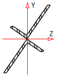
- The
T parameter stands for a T-shaped section obtained
by cutting an I-shaped section at exactly its mid height level along the web.
Hence, the area of a T shape is exactly half the area of the corresponding I
shape. The depth of a T shape is half the depth of the I shape it was cut from.
What we refer to as I shaped sections are sections which look like the English alphabet I. The American Wide Flange, the British UB and UC sections, Japanese H sections, etc., all fall under this category. Consequently, the 'T' shape cut from a Japanese H shape is one obtained by cutting the H shape at exactly its mid-height level of the web.
Not all I shaped sections have a corresponding T. This may be inferred by going through the section libraries of individual countries and organizations. In such cases, if a user were to specify such a T section, the program will terminate with the message that the section does not exist.
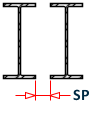
- Steel Cover plates also can be added only to I shaped sections. Thus, the TC, BC, and TB are not applicable to any shape other than an I shape.