D9.B.3 Design Parameters
| Parameter Name | Default Value | Description |
|---|---|---|
| CODE | - |
Must be specified as JAPANESE 2005 to invoke the AIJ 2005. Design code to follow. See TR.48.1 Parameter Specifications. |
| BEAM | 1.0 |
Locations of design:
|
| CAN | 0 | Specifies the method used for
deflection checks
|
| CB | 0 |
C value from the AIJ code. Refer to D9.B.2 Member Capacities - Bending Stress for how C is calculated and applied. Use 0.0 to direct the program to calculated Cb. Any other value be used in lieu of the program calculated value. |
| DFF | None(Mandatory for deflection check) | "Deflection Length" / Maximum allowable local deflection |
| DJ1 | Start Joint of member | Joint No. denoting starting point for calculation of "Deflection Length" (See note b) |
| DJ2 | End Joint of member | Joint No. denoting end point for calculation of "Deflection Length"(See note b) |
| DMAX | 100 cm | Maximum allowable depth for member. |
| DMIN | 0.0 cm | Minimum allowable depth for member. |
| FYLD | 235 MPa | Yield strength of steel in megapascals. The material strength value is first take from the FYLD parameter if specified. If FYLD has not been specified, then the value in the material definition are used. If no material definition has been assigned, then the default parameter value of Fy = 235 MPa is assumed. |
| KY | 1.0 | K value in local y-axis. Usually, this is the minor axis. |
| KZ | 1.0 | K value in local z-axis. Usually, this is the major axis. |
| LY | Member Length | Length in local y-axis to calculate slenderness ratio. |
| LZ | Member Length | Same as above except in z-axis |
| MAIN | 200 | Allowable
Slenderness Limit for Compression Member
Any value greater than 1 = Allowable KL/r in compression (up to 250) |
| MBG | 0 | Specifies how to calculate the
section modulus about the Z-Z axis for H-shape, I-shape, and channel sections
when performing major axis bending checks:
|
| MISES | 1 | Von Mises check options:
|
| NSF | 1.0 | Net section factor for tension members. |
| PLB | 0 |
Plastic critical slenderness ratio. If this is 0 (the default value), it will be calculated according to AIJ 2005 eqn. 5.12 or 5.14. Any other entered value will be used as the value of p-lambda-b. |
| RATIO | 1.0 | Permissible ratio of the actual to allowable stresses. |
| SLF | 1 | Slender section design option:
|
| TMAIN | 400 |
Allowable Slenderness Limit for Tension Member
Any value greater than 1 = Allowable KL/r in tension. |
| TRACK | 0.0 |
Level of output detail:
|
| UNF | 1.0 | Unsupported length provided as a fraction of actual member length used for lateral-torsional buckling calculation. |
| UNL | Member Length | Unsupported length for calculating allowable bending stress. Used for the lateral-torsional buckling calculation. Value should be in the current units of length. |
D9.B.3.1 Notes
-
When performing the deflection check, you can choose between two methods. The first method, defined by a value 0 for the CAN parameter, is based on the local displacement. Refer to TR.44 Printing Section Displacements for Members for details on local displacement..
If the CAN parameter is set to 1, the check will be based on cantilever style deflection. Let (DX1, DY1,DZ1) represent the nodal displacements (in global axes) at the node defined by DJ1 (or in the absence of DJ1, the start node of the member). Similarly, (DX2, DY2, DZ2) represent the deflection values at DJ2 or the end node of the member.
Compute Delta =
Compute Length = distance between DJ1 and DJ2 or, between start node and end node, as the case may be.
Then, if CAN is specified a value 1, dff = L/Delta
Ratio due to deflection = DFF/dff
-
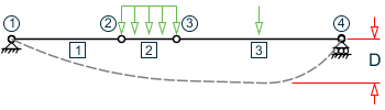
If CAN = 0, the "Deflection Length" is defined as the length that is used for calculation of local deflections within a member. It may be noted that for most cases the "Deflection Length" will be equal to the length of the member. However, in some situations, the "Deflection Length" may be different. A straight line joining DJ1 and DJ2 is used as the reference line from which local deflections are measured.
For example, refer to the figure below where a beam has been modeled using four joints and three members. The "Deflection Length" for all three members will be equal to the total length of the beam in this case. The parameters DJ1 and DJ2 should be used to model this situation. Thus, for all three members here, DJ1 should be 1 and DJ2 should be 4. D = Maximum local deflection for members 1, 2, and 3.PARAMETERS DFF 300. ALL DJ1 1 ALL DJ2 4 ALL
- If DJ1 and DJ2 are not used, "Deflection Length" will default to the member length and local deflections will be measured from original member line.
- The above parameters may be used in conjunction with other available parameters for steel design.