D5.D.5.2 Clause 6.3.2.2 –Elastic critical moment and imperfection factors for LTB checks
The UK-NA recommends the use of Table 6.3 and 6.4 of BS EN 1993-1-1:2005 to calculate the imperfection factors for Lateral Torsional Buckling (LTB) checks.
The calculation of the LTB reduction factor χLT, requires the calculation of the "Elastic Critical Buckling Moment", Mcr. The UK National Annex does not specify a particular method to calculate Mcr. Hence the calculation of Mcr has been based on the following NCCI documents:
SN003a-EN-EU – Elastic critical moment for Lateral torsional Buckling:
This document provides a method to calculate "Mcr" specifically for doubly symmetric sections only. Hence only doubly symmetric sections will be considered for this method in the proposed implementation.
The equation to evaluate Mcr is given in the NCCI as:
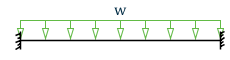
C1 and C2 are factors that depend on the end conditions and the loading conditions of the member. The NCCI provides values for C1 and C2 for the different cases as given in the tables below:

| Loading and support conditions | Bending moment diagram | C1 | C2 |
|---|---|---|---|
 |
 |
1.127 | 0.454 |
|

|
2.578 | 1.554 |

|

|
1.348 | 0.630 |

|

|
1.683 | 1.645 |
This NCCI considers three separate loading conditions:
- Members with end moments
- Members with transverse loading
- Members with end moments and transverse loading.
The implementation of EC3 in STAAD.Pro accounts for the loading condition and the bending moment diagram through the CMM parameter. The first two loading conditions mentioned above and its variants can be dealt with by using the existing values of the CMM parameter (i.e., 1 to 6). Hence the appropriate values from this NCCI will be used for "C1" and ‘C2’ coefficients depending on the value of CMM specified. The default value of CMM is 1, which considers the member as a pin ended member with UDL along its span. The user will also have the option to specify specific values for C1 and C2 using the C1 and C2 parameters in the design input mode. Refer to D5.C.6 Design Parameters
However, for cases with end moments and transverse loading, the NCCI provides graphs to evaluate the C1 and C2 coefficients. It does not however, provide a set of equations for these graphs. However the "end moments and transverse loading" condition cannot be currently specified in the design input. Hence this implementation will introduce two new values for the CMM parameter viz.
CMM 7: Member with varying end moments and uniform loading.
CMM 8: Member with varying end moments and central point load.
For these two conditions, the UK National Annex (nor the NCCI) does not provide equations to evaluate C1 and C2. Hence in STAAD.Pro the user will have to use the new "C1" & ‘C2’ parameters to input the required values for C1 & C2 to be used in calculating Mcr. For values of 7 or 8 for the CMM parameter, the program will issue a warning if C1 and C2 have not been specified.
SN030a-EN-EU – Mono-symmetrical uniform members under bending and axial compression:
This document provides a method to evaluate the elastic critical moment (Mcr) for uniform mono symmetric sections that are symmetric about the weak axis. Hence for this implementation the elastic critical moment for "Tee-Sections" will be worked out using the method in this NCCI.
Note: Though this method could also be applicable to mono-symmetric built-up sections, STAAD.Pro does not have a means to specify/identify a mono-symmetric built-up section. Hence this implementation will use this method only for Tee-Sections. In any case, the actual LTB capacity will still be worked out as per BS 5950-1 as in the current EC3 implementation.
The equation to evaluate Mcr for mono symmetric sections is given as :
The factors C1, C2, and C3 are dependent on the end conditions and loading criteria. This implementation will consider C1, C2, and C3as given in the tables below:

The CMM parameter (see section (i) above) specified during design input will determine the values of C1, C2 and C3. The default value of CMM is 1, which considers the member as a pin ended member with UDL along its span. This NCCI does not however consider the end moments and transverse loading condition. The user however can use the new C1, C2 and C3 parameters to input the required values for C1, C2 and C3 to be used in calculating Mcr. As described in section (i) above, the user must use C1, C2 and C3 parameters along with CMM values of 7 and 8.
Both the NCCI documents mentioned above assume that the member under consideration is free to rotate on plan and that there are no warping restraints for the member ( k = kw = 1.0). The current implementation of EC3 in STAAD takes into account of the end conditions using the CMN parameter. A value of K = kw =1 is indicated by a value of CMN = 1.0 in the design input. Hence the above methods will be used only for members which are free to rotate on plan and which have no warping restraints, i.e., CMN = 1.0. For members with partial or end fixities (ie, CMN = 0.5 or CMN = 0.7), the proposed implementation will fall back on to the method and coefficients in DD ENV 1993-1-1:1992 – Annex F.
For all cases that are not dealt with by the National Annex (or the NCCI documents) the proposed implementation will use the method as per the DD ENV 1993-1-1:1992 code.
The term "zg" in the equation to calculate Mcr refers to the distance between the point of application of load on the cross section in relation to the shear center of the cross section. The value of ‘zg’ is considered positive if the load acts towards the shear center and is negative if it acts away from the shear center. By default, the program will assume that the load acts towards the shear center at a distance equal to (Depth of section/2) from the shear center. The user will be allowed to modify this value by using the new ‘ZG’ parameter. Specifying a value of ZG = 0 in the design input would indicate that the load acts exactly at the shear center of the section so that the term ‘zg’ in the equation will have a value of zero.