D1.A.6 Design Parameters
Design per AISC 360-05, 360-10, and 360-016 (Unified) specifications is requested by using the CODE parameter. Other applicable parameters are summarized in the following Table. These parameters communicate design decisions from the engineer to the program and thus allow you to control the design process.
The default parameter values have been selected such that they are frequently used numbers for conventional design. Depending on the particular design requirements, some or all of these parameter values may be changed to exactly model the physical structure.
| Parameter Name | Default Value | Description |
|---|---|---|
| CODE | AISC UNIFIED |
Used to designate this code (default is the 2016 edition). CODE AISC UNIFIED (2016) CODE AISC UNIFIED 2010 CODE AISC UNIFIED 2005 |
|
ALH
(AISC 360-16 only) |
0.5 | Distance of applied point torsion
from start of member as a fraction of member length. Represented by
"
α
" in the torsional case options in Appendix B of AISC Design
Guide 9.
To be used with TND values of 3, 6, or 9. (0<ALH<1). Set TORSION 1 to enable Torsion check as per DG9. |
| BEAM | 1.0 |
See Note 9 below.
|
|
BRC
(AISC 360-05 and 360-10 only) |
1 |
Specifies the bracing type for the member used for seismic provision checks:
|
| CAN | 0 |
0 = deflection check based on the principle that maximum deflection occurs within the span between DJ1 and DJ2. 1 = deflection check based on the principle that maximum deflection is of the cantilever type (see D1.B.1.2 Design Parameters) |
| CB 2 | 1.0 | Coefficient Cb per Chapter F. If Cb is set to 0.0, it will be calculated by the program. Any other value will be directly used in the design. See Note 2 below. |
| CSPACING | 12 in | Spacing between connectors in current length units. Refer to Section E6.1 and E6.2 of AISC 360. |
| DFF | none (mandatory for deflection check) |
"Deflection Length" / Maximum allowable local
deflection. See TR.40 Load Envelope for deflection checks using serviceability load envelopes. |
| DJ1 | Start Joint of member | Joint No. denoting starting point for calculation of "Deflection Length" (see D1.B.1.2 Design Parameters) |
| DJ2 | End Joint of member | Joint No. denoting end point for calculation of "Deflection Length" (see D1.B.1.2 Design Parameters) |
| DMAX | 1000.0 mm | Maximum allowable depth for member selection. |
| DMIN | 0.0 mm | Minimum allowable depth for member selection. |
|
DUCT
(AISC 360-16 only) |
0 | The ductile category of the
member as per AISC 341-16:
|
| E5PROVISION (AISC 360-16 only) |
0 | Specifies whether the requirements for single angle members in
compression in sections E5.(1) to E5.(3) are met for this member.
See Note 11 below for details. |
| FLX | 1 |
Parameter for specifying the lateral-torsional restraint condition for a single angle. Refer to Section F10 of AISC 360-05, 360-10, and 3601-16.
|
|
FRM
(AISC 360-05 and 360-10 only) |
0 |
Specifies the seismic force-resisting system used in seismic provision checks:
|
| FU | 400 MPa | Ultimate strength of steel. |
| FYLD | 250 MPa | Yield strength of steel. The program considers a valid range of input values between 10 ksi - 100 ksi (69 MPa - 689 MPa). |
| IMM (AISC 360-16 only) |
0 | Truss type of single angle members:
Note: For the default case, a single angle is assumed to be an
individual or web member of a planar truss [E5(a)] with adjacent web
members attached to the same side of the gusset plate or
chord.
See Note 11 below for additional details. |
| KX | 1.0 | K value for flexural-torsional buckling. |
| INTERACTION | 0 |
Directs the program which interaction equations to check per section H1:
|
| KY | 1.0 | Effective length factor to calculate slenderness ratio for compression buckling about local y-axis. Usually this is the minor axis. |
| KZ | 1.0 | Effective length factor to calculate slenderness ratio for compression buckling about local z-axis. Usually this is the major axis. |
|
LBRC
(AISC 360-16 only) |
1 |
Type of flange lateral bracing:
Used to calculate bracing requirements as per seismic provisions in AISC 341-16. |
| LEG | 0 |
This parameter is meant for plain angles (Section E5).
|
| LX | Member Length | Length for flexural-torsional buckling. See Note 8 below. |
| LY | Member Length | Length to calculate slenderness ratio for buckling about local y-axis. |
| LZ | Member Length | Length to calculate slenderness ratio for buckling about local z-axis. |
| MAIN | 200 | Allowable slenderness limit for compression members. A value of 1 suppresses this check. Any value greater than 1 is used as the compression slenderness check value. |
| METHOD | LRFD | Used to specify LRFD or ASD design methods. |
| MTYP | 1 |
Specifies whether the member is a beam or column. Used for seismic provisions checks.
For AISC 360-16 only:
|
|
NBRC
(AISC 360-16 only) |
1 | Number of braced points within the span. Represented by "n" in Appendix 6.3.2(a) of AISC 360-16. Required for Seismic Provisions. |
| NSF | 1.0 | Net Section Factor for tension members, equal to An/Ag ,used to account for reduction in section used for tension checks (clause B 4.3b.) combined with the SLF parameter to determine the rupture strength. (see also SLF parameter) |
| PROFILE | Used in member selection. Refer to TR.48.1 Parameter Specifications for details. | |
| RATIO | 1.0 | Permissible ratio of actual load to allowable strength. |
| SEISMIC | 0 | Used to instruct the program to add additional checks per the
AISC 341, Seismic Provisions for Structural Steel
Buildings.
AISC 360 – 05, check according to AISC 341 – 05 AISC 360 – 10, check according to AISC 341 – 10 AISC 360 – 16, check according to AISC 341 – 16 See section D1.A. American Codes - Steel Design per AISC 360 Unified Specification for more details.
See D1.A.9 Seismic Provision Checking per AISC 341 for details. |
|
SGR
(AISC 360-16 only) |
Used to specify material strength by ASTM steel grades.
The yield stress and ultimate stress will be auto-calculated based on the
grade selected. Note that any SGR value greater
than 0 will take priority when calculating the yield stress and
ultimate stress over any supplied FYLD and
FU value.
|
|
| SLF | 1.0 | Shear Lag Factor, value " U " normally taken from table D3.1, combined with the NSF parameter to determine the net effective area used to calculate the section rupture strength. (see also NSF parameter) |
| SNUG | 1 |
Type of connection for the built-up members:
|
|
SOE
(AISC 360-16 only) |
0 | Second Order Effects have been
considered in analysis forces or not:
By default, Second Order Effects are not considered in the analysis forces. This is related to Torsion checks as per DG9. Set TORSION 1 to enable Torsion check as per DG9. |
| SRT (AISC 360-16 only) |
0 | Used for tension slenderness checking.
For default case, tension slenderness check is made by dividing the TSL value by Rmin. For SRT value 1, slenderness design for tension member will be done by taking maximum length out of LZ, LY and member length. |
|
STFB
(AISC 360-16 only) |
0.0 | Stiffener width for one-sided web stiffeners, twice the individual stiffener width for pairs of stiffeners. Represented by "bs" in Appendix 6.3.2(a) of AISC 360-16. Required for Seismic Provisions. |
|
STFT
(AISC 360-16 only) |
0.0 | Thickness of web stiffeners. Represented by "tst" in Appendix 6.3.2(a) of AISC 360-16. Required for Seismic Provisions. |
| STIFF | Member Length or depth of beam, whichever is greater | Spacing of stiffeners for plate girder design. |
| STP | 1.0 | Section Type used for
design
|
|
TBRC
(AISC 360-16 only) |
Type of torsional bracing:
Used to calculate bracing requirements as per seismic provisions in AISC 341-16. |
|
|
TFA
(AISC 360-16 only) |
0 | Tension field action to be
considered in shear design:
|
| TSL (AISC 360-16 only) |
Member Length | The length used in tension slenderness checks. |
| TMAIN | 300 | Allowable slenderness limit for tension members. A value of 1 suppresses this check. Any value greater than 1 is used as the tension slenderness check value. |
|
TND
(AISC 360-16 only) |
1 |
Torsion loading and end condition as in Table in Appendix C.4 of AISC Design Guide 9:
The number corresponds to the case number of the case chart in Appendix B of DG9. Set TORSION 1 to enable Torsion check as per DG9. |
|
TORSION
(AISC 360-10 and 360-16 only) |
0 |
Specifies design for torsion per AISC Design Guide 9. See D1.A.5.6 Design for Torsion
|
| TRACK | 0 |
Specifies the amount of detail included in design output
|
| UNB | Member Length | Unsupported length of the bottom flange for calculating flexural strength. Will be used only if compression is in the bottom flange. See Note 3 below. |
| UNL | Member Length | Unsupported length of left extreme flange for LTB that will be used as lateral-torsional buckling length for the section with the vertical axis as major principal axis and where the left extreme fiber is in compression. If member is assigned with any value of UNL and FLX=2 concurrently, LTB length of the member will be treated as zero. |
| UNR | Member Length | Unsupported length of right extreme flange for LTB that will be used as Lateral-torsional buckling length for the section with the vertical axis as major principal axis and where the right extreme fiber is in compression. If member is assigned with any value of UNR and FLX=2 concurrently, LTB length of the member will be treated as zero. |
| UNT | Member Length | Unsupported length of the top flange for calculating flexural strength. Will be used only if compression is in the top flange. See Note 3 below. |
|
WTYPE
(AISC 360-05 and 360-10 only) |
0 |
Weld type for HSS per Sect. B3.12 (AISC 360-05) or Sect. B4.12 (AISC 360-10):
For HSS Rectangle and Round profiles from AISC databases, the weld type will always be determined based on profile table (grade A1085 or not). WTYP will have no effect on these. For any other hollow profiles (pipe, tube, box, etc.) from AISC databases, all hollow profiles from any other country databases, and User Provided tables, the weld type must be specified using the WTYP parameter. |
Notes
-
For the AISC 360 unified code, an angle is automatically checked for geometric axis bending (in addition to principal axis bending) provided one of the following conditions is met:
The AXIS parameter is only used by the deprecated AISC 360-05 code checking method (CODE AISC UNIFIED OLD). If this code is used, then AXIS 1 specifies design based on principle axes, where AXIS 2 specifies design based on geometric axes.
- Non-default values of CB must be re-entered before every subsequent CHECK CODE or SELECT command.
- Top and Bottom represent the positive and negative side of the local Y axis (local Z axis if SET Z UP is used).
- For a description of the deflection check parameters DFF, DJ1, DJ2 see the Notes section of D1.B.1.2 Design Parameters of this manual.
- NSF is the Net Section Factor as used in most of the steel design codes in STAAD.Pro. It is defined as the Ratio of "Net cross section area" / "Gross section area" for tension member design. The default value is 1.0. For the AISC 360 code, it is described in section D.3.2.
- SLF is the Shear Lag Factor, as used in Section D.3.3 of the AISC 360-05 code. This factor is used to determine the effective net area by multiplying this factor with net area of the cross section. Please refer to Table D3.1 of the 360 code for a list of acceptable SLF values. In STAAD.Pro, the default value for SLF is 1.0. The effective net area is used to determine the tensile strength for tensile rupture in the net section, as per equation D.2.2.
- To summarize, the "Gross Area" (Ag) is multiplied by NSF to get the "Net Area" (An) of the section. The "Net Area" (An) is then multiplied by SLF to get the "Effective Net Area" (Ae) of the section.
- For the design of a single angle for flexure, the parameter LX should be used to specify the value of the term "L" in equations F10-4a, F10-4b, F10-5 and F10-6 of AISC 360-05 and the term "Lb" in equations F10-4, F10-5, F10-6a, and F10-6b of AISC 360-10.
-
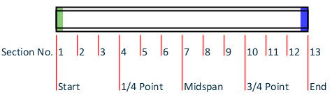
When BEAM is 1.0 (default), the design is performed at 13 evenly spaced points along the length of the beam, including start and end points (i.e., 1/12th points or at ends of 12 equal length segments).
When BEAM is 0.0, the start and ends along with up to three locations specified in TR.41 Section Specification are designed.
- For AISC 360-16, the material strength values are first taken from the
SGR parameter if specified (and not zero). The specify
values for each SGR value are given in the following table. If
SGR has not been specified, then the values of the
FYLD and FU parameters will be used if
specified. If no design parameters have been specified for material strengths,
then the values in the material definition are used. If no material definition
has been assigned, then the STAAD.Pro default values of
Fy = 36 ksi and Fu = 58 ksi are
assumed.
Table 2. SGR values and corresponding material strength values for AISC 360-16 SGR ASTM Grade Fy (ksi) Fu (ksi) 1 A36 36 58 2 A53GrB 35 60 3 A500 Gr.B (HSS Rect) 46 58 4 A500 Gr.B (HSS Round) 42 58 5 A500 Gr.C (HSS Rect) 50 62 6 A500 Gr.C (HSS Round) 46 62 7 A501 Gr.A 36 58 8 A501 Gr.B 50 70 9 A529 Gr.50 50 100
65* (if thickness > 1.5 in)
10 A529 Gr.55 55 100
70*(if thickness > 1.5 in)
11 A709 Gr.36 36 58 12 A1043 Gr.36 36 58 13 A1043 Gr.50 50 65 14 A572 Gr.42 42 60 15 A572 Gr.50 50 65 16 A572 Gr.55 55 70 17 A572 Gr.60 60*(if thickness <= 2.0 in) 75*(if thickness <= 2.0 in) 18 A572 Gr.65 65*(if thickness <= 2.0 in) 80*(if thickness <= 2.0 in) 19 A618 Gr.Ia.Ib & II 50
46*(if thickness > 0.75 in)
70
67*(if thickness > 0.75 in)
20 A618 Gr.III 50 65 21 A709 Gr.50 50 65 22 A709 Gr.50S 50 65 23 A709 Gr.50W 50 70 24 A913 Gr.50 50 65 25 A913 Gr.60 60 75 26 A913 Gr.65 65 80 27 A913 Gr.70 70 90 28 A992 50 65 29 A588 50 70 30 A847 50 70 31 A1085 50 65 - For AISC 360-16, single angle members in compression can be designed using a modified slenderness method provided a set of conditions are met for that member. It is left to the engineer to confirm that conditions E5.(1) through E5.(3) are met and to specify this for single angle member using the E5P parameter. Those conditions are:
- 1) Members are loaded at the ends in compression through the same leg.
- 2) Members are attached by welding or by connections with a minimum of two bolts.
- 3) There are no intermediate transverse loads.
The effective slenderness ratio method used for single angles also depends on if those angle members are:- individual members or are web members of planar trusses (in which case, Cl. E5(a) applies - IMM 0)
- web members of box or space trusses (in which case, Cl. E5(b) applies - IMM 1)