M.To create an I shape user table section
To create a user-provided table section with an I section profile, including those with composite flanges or tapered web depth, use the following procedure.
You may want to change the input dimensions prior to creating user provided table sections. Select to do so.
This user-provided section allows you to specify a tapered I-Section with an optional composite top flange. For I sections with a bottom steel plates, you must create a prismatic wide flange section. Alternatively, you may use a tapered I section when a non-composite section is required.
-
On the
Specification ribbon tab, select the
tool in the
Beam Profiles group.

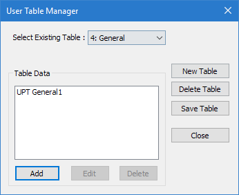
If no User Defined Table exists, you will be prompted to create one.
The User Table Manager dialog opens. - Click New Table. The New User Table dialog opens.
- the Select Section Type list, select ISECTION and then click OK. The dialog closes and the Table Data list in the User Table Manager dialog now has at least one entry.
-
Click Add.
The I Section dialog opens.
- Type a Section Name.
- Required: Enter the following wide flange section parameters:
- (Optional)
To specify a composite top flange:
- Check the Additional Composite Flange option. The Additional Composite Flange Specifications become active.
- Specify the following values:
- (Optional)
Specify the section properties Torsional Constant (Ix),
Shear Area in Y (Ay), and Shear Area in Z
(Az):
To… Do the following… specify section properties directly type positive values in these fields specify factors to use for calculated properties type negative values for the factors in each field use calculated properties leave each field as zero (0) The remaining section properties are calculated at finite points along the section for use in the analysis.
- Click OK.
- (Optional) Repeat steps 4 through 9 to add more I sections.
- Click Close.

The section can now be added for use in the Properties - Whole Structure dialog by selecting it in the User Property Table dialog.