V. AISC 360-05 Tapered I Section
Verify the axial compression capacity, flexure capacity, and interaction ratio of a tapered I section member per both the LRFD and ASD methods of the AISC 360-05 code.
Details
A 5' × 5' portal frame consists of W12x72 columns and a steel tapered member for the beam.
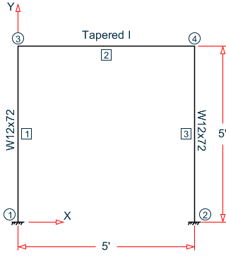
- A uniformly distributed load of -3.5 k/ft along the beam in the global Y direction.
- Lateral loads at the top of the left column of 50 kips in the global X direction and 25 kips in the global Z direction (out of plane).
- Lateral loads at the top of the right column of -50 kips in the global X direction and 45 kips in the global Z direction (out of plane).
- A concreted load of -100 kips in the global Y direction and a concentrated torque of 9 in·kips at mid-span of the beam.
- E = 29,000 ksi
- Fy = 50 ksi
Validation
Design Forces
- Mz = 32.26 in·kips, Fy = 8.755 kips
- Mz = 677.6 in·kips, My = 2.942 in·kips, Mx = 5.106 in·kips, Fy = 22.98 kips, Fz = 0.098 kips, Fx = 24.70 kips
- Mz = 275.9 in·kips, Mx = 4.497 in·kips, Fy = 50.23 kips, Fx = 5.473 kips
- Mz = 654.5 in·kips, My = 5.298 in·kips, Mx = 9.192 in·kips, Fy = 22.50 kips, Fz = 0.177 kips, Fx = 24.35 kips
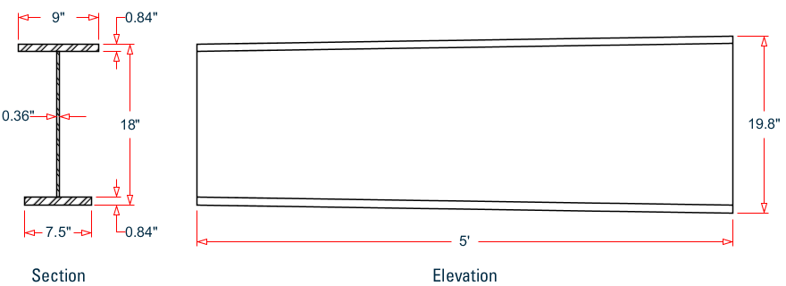
Section Properties
The section at the left end (D = 18 in.) has the following properties:
- Web height, dw = 18 - 2×0.84 = 16.32 in.
- Area, Ag = (0.84)(9 + 7.5) + 16.32 (0.36) = 19.74 in2
- Shear area in local y, Avy = 18(0.36) = 6.48 in2
- Shear area in local x, Avx = 0.84(9 + 7.5) = 13.86 in2
- Dist to centroid y,
- Moment of inertia about major axis,
- Moment of inertia about minor axis,
- Elastic section modulus about major axis top flange fiber,
- Elastic section modulus about major axis bottom flange fiber,
- Elastic section modulus about minor axis,
- Radius of gyration about major axis,
- Radius of gyration about minor axis,
- Location of the plastic neutral axis,
- Plastic section modulus about major axis,
- Plastic section modulus about minor axis,
- Torsional constant,
Section Classification
Flange in compression
Per Table B4.1a, , therefore flanges are non-slender for compression.
Web in compression
Per Table B4.1a, Case 5, , therefore the web is slender for compression.
Flange in bending (use half the longer flange width as the outstanding width):
Per Table B4.1b, Case 11, , therefore flange is compact for bending.
Web in bending
Per Table B4.1b, Case 15, , therefore web is compact for bending.
Compression Capacity
About X Axis:
| (Eq. E3-4) |
| (Eq. E3-2) |
Since the web is slender, use the effective area. The effective width imperfection adjustment factors (Table E7.1):
c1 = 0.18
c2 = 1.31
| (Eq. E7-5) |
Therefore, the effective depth of the web in compression for the effective area:
| (Eq. E7-3) |
The reduced area of the section then becomes:
| Pnx = Ae× Fcrx = 18.84 × 49.77 = 937.4 kips | (Eq. E7-1) |
About Y Axis:
| (Eq. E3-4) |
| (Eq. E3-2) |
Therefore, the effective depth of the web in compression for the effective area:
| (Eq. E7-3) |
The reduced area of the section then becomes:
| Pny = Ae× Fcry = 18.93 × 46.88 = 887.4 kips | (Eq. E7-1) |
- The ultimate compression capacity (LRFD) = ϕcPn = 0.9 × 887.4 = 798.3 kips
- The allowable compression capacity (ASD) = Pn/Ωc = 887.4 / 1.67 = 531.4 kips
Calculate Bending Capacity
Bending capacity in plastic yielding about Y axis:
My = Fy × Zy = 50 × 29.35 = 1,468 in·kips > 1.6Fy × Sy = 1.6 (50) (17.92) = 1,434 in·kips
Use My =1,434 in·kips
- The ultimate bending capacity (LRFD) = ϕbMy = 0.9 × 1,434 = 1,290 in·kips
- The allowable bending capacity (ASD) = My/Ωb = 1,434 / 1.67 = 858.4 in·kips
Bending capacity in plastic yielding about X axis:
The section is capacity is determined as per F4 in the specification. The design moments for this are from Load Case 4 and occur at mid-span (d = 18.9 in.). The section properties at this location are:
- Izz = 1,278 in4
- Iyy = 80.63 in4
- c = 10.01 in
- hc = 2×(10.01 - 0.84) = 18.35 in.
- Sx = 143.8 in3
- Zx = 150.7 in3
Myc = Fy × Syc = 50 × 143.8 = 7,192 ksi
Mp = Fy × Zx = 50 × 150.7 = 7,535 ksi ≤ 1.6 Fy × Sx = 11,504 ksi
The moment of inertia of the compression flange about the Y axis , and thus . (limiting slenderness for a compact web per Table B4.1b case 15), so the web plastification factor, Rpc is determined as:
| (F4-9a) |
Bending capacity in plastic yielding about Y axis:
Mn = Rpc × Myc = 1.048 × 7,192 = 7,535 in·kips
- The ultimate bending capacity (LRFD) = ϕbMy = 0.9 × 7,535 = 6,782 in·kips
- The allowable bending capacity (ASD) = My/Ωb = 7,535 / 1.67 = 4,512 in·kips
Interaction Ratio for Bending and Compression
Check the interaction ratio for Load Case 3:
So use Eq. H1-1b for both methods: .
Results
| Result Type | Reference | STAAD.Pro | Difference | Comments | |
|---|---|---|---|---|---|
| LRFD | Compression capacity (kips) | 798.3 | 799 | negligible | |
| Major axis bending capacity (in·kips) | 6,782 | 6,780 | negligible | ||
| Minor axis bending capacity (in·kips) | 1,290 | 1,290 | none | ||
| Interaction ratio | 0.184 | 0.184 | none | ||
| ASD | Compression capacity (kips) | 531.4 | 532 | negligible | |
| Major axis bending capacity (in·kips) | 4,512 | 4,510 | negligible | ||
| Minor axis bending capacity (in·kips) | 858.4 | 858 | negligible | ||
| Interaction ratio | 0.277 | 0.277 | none | ||
STAAD.Pro Input
The following design parameters are used:
The remaining parameters all use their default values.
The file C:\Users\Public\Public Documents\STAAD.Pro CONNECT Edition\Samples\ Verification Models\09 Steel Design\US\AISC\AISC 360-05 Tapered I Section.STD is typically installed with the program.
STAAD SPACE
START JOB INFORMATION
ENGINEER DATE 14-Jan-21
END JOB INFORMATION
INPUT WIDTH 79
UNIT FEET KIP
JOINT COORDINATES
1 0 0 0; 2 0 5 0; 3 5 0 0; 4 5 5 0;
MEMBER INCIDENCES
1 1 2; 2 2 4; 3 3 4;
DEFINE MATERIAL START
ISOTROPIC STEEL
E 4.176e+06
POISSON 0.3
DENSITY 0.489024
ALPHA 6.5e-06
DAMP 0.03
TYPE STEEL
STRENGTH RY 1.5 RT 1.2
END DEFINE MATERIAL
MEMBER PROPERTY
2 TAPERED 1.5 0.03 1.65 0.75 0.07 0.625 0.07
MEMBER PROPERTY AMERICAN
1 3 TABLE ST W12X72
CONSTANTS
MATERIAL STEEL ALL
SUPPORTS
1 3 FIXED
LOAD 1 LOADTYPE None  TITLE LOAD CASE 1
MEMBER LOAD
2 UNI GY -3.5
LOAD 2 LOADTYPE None  TITLE LOAD CASE 2
JOINT LOAD
2 FX 50 FZ 25
LOAD 4 LOADTYPE None  TITLE LOAD CASE 4
JOINT LOAD
4 FX -50 FZ 45
LOAD 3 LOADTYPE None  TITLE LOAD CASE 3
MEMBER LOAD
2 CON GY -100
2 CMOM GX 0.75
PERFORM ANALYSIS
PRINT ANALYSIS RESULTS
UNIT INCHES KIP
PARAMETER 1
CODE AISC UNIFIED 2005
FYLD 50 ALL
FU 60 ALL
METHOD LRFD
STP 2 MEMB 2
TRACK 2 MEMB 2
CHECK CODE MEMB 2
PARAMETER 2
CODE AISC UNIFIED 2005
FYLD 50 ALL
FU 60 ALL
METHOD ASD
STP 2 MEMB 2
TRACK 2 MEMB 2
CHECK CODE MEMB 2
FINISH
STAAD.Pro Output
STAAD.PRO CODE CHECKING - (AISC-360-05-LRFD) v3.3a ******************************************** ALL UNITS ARE - KIP INCH (UNLESS OTHERWISE Noted) MEMBER TABLE RESULT/ CRITICAL COND/ RATIO/ LOADING/ FX MY MZ LOCATION ======================================================================= 2 TAPERED (AISC SECTIONS) PASS Sec. G1 0.286 3 5.47 C 0.00 275.86 0.00 |-----------------------------------------------------------------------| | SLENDERNESS | | Actual Slenderness Ratio : 29.685 L/C : 3 | | Allowable Slenderness Ratio : 200.000 LOC : 0.00 | |-----------------------------------------------------------------------| | STRENGTH CHECKS | | Critical L/C : 3 Ratio : 0.286(PASS) | | Loc : 0.00 Condition : Sec. G1 | |-----------------------------------------------------------------------| | DESIGN FORCES | | Fx: 5.473E+00(C ) Fy: 5.002E+01 Fz: 0.000E+00 | | Mx: -4.497E+00 My: 1.731E-05 Mz: 2.759E+02 | |-----------------------------------------------------------------------| | SECTION PROPERTIES (UNIT: INCH) | | Azz: 1.386E+01 Ayy: 6.480E+00 Cw: 5.508E+03 | | Szz: 1.200E+02 Syy: 1.792E+01 | | Izz: 1.146E+03 Iyy: 8.062E+01 Ix: 3.514E+00 | |-----------------------------------------------------------------------| | MATERIAL PROPERTIES | | Fyld: 50.000 Fu: 60.000 | |-----------------------------------------------------------------------| | Actual Member Length: 60.000 | | Design Parameters | | Kz: 1.00 Ky: 1.00 NSF: 1.00 SLF: 1.00 CSP: 12.00 | |-----------------------------------------------------------------------| | SECTION CLASS UNSTIFFENED / λ λp λr CASE | | STIFFENED | | Compression : Non-Slender 5.36 N/A 11.88 T.B4.1-4 | | Slender 45.33 N/A 35.88 T.B4.1-10 | | Flexure : Compact 5.36 9.15 21.15 T.B4.1-2 | | Compact 44.73 94.06 137.27 T.B4.1-11 | STAAD SPACE -- PAGE NO. 8 STAAD.PRO CODE CHECKING - (AISC-360-05-LRFD) v3.3a ******************************************** ALL UNITS ARE - KIP INCH (UNLESS OTHERWISE Noted) |-----------------------------------------------------------------------| | CHECK FOR AXIAL TENSION | | | | FORCE CAPACITY RATIO CRITERIA L/C LOC | | Yield 0.00E+00 8.88E+02 0.000 Eq. D2-1 1 0.00 | | Rupture 0.00E+00 8.88E+02 0.000 Eq. D2-2 1 0.00 | |-----------------------------------------------------------------------| | CHECK FOR AXIAL COMPRESSION | | | | FORCE CAPACITY RATIO CRITERIA L/C LOC | | Maj Buck 2.47E+01 8.41E+02 0.029 Sec. E1 2 0.00 | | Min Buck 2.47E+01 7.99E+02 0.031 Eq. E7-1 2 0.00 | | Flexural | | Tor Buck 2.47E+01 7.93E+02 0.031 Eq. E7-1 2 0.00 | | Intermediate | | Results Eff Area KL/r Fcr Fe Pn | | Maj Buck 1.88E+01 7.88 4.74E+01 4.62E+03 9.35E+02 | | Min Buck 1.89E+01 29.69 4.50E+01 3.25E+02 8.88E+02 | | Flexural Ag Fcr Pn | | Tor Buck 1.89E+01 4.46E+01 8.81E+02 | |-----------------------------------------------------------------------| | CHECK FOR SHEAR | | | | FORCE CAPACITY RATIO CRITERIA L/C LOC | | Local-Z 1.77E-01 3.74E+02 0.000 Eq. G2-1 4 0.00 | | Local-Y 5.00E+01 1.75E+02 0.286 Eq. G2-1 3 0.00 | | Intermediate | | Results Aw Cv Kv h/tw Vn | | Local-Z 1.39E+01 1.00 1.20 10.71 4.16E+02 | | Local-Y 6.48E+00 1.00 5.00 45.33 1.94E+02 | |-----------------------------------------------------------------------| | CHECK FOR BENDING-YIELDING | | | | FORCE CAPACITY RATIO CRITERIA L/C LOC | | Major 1.22E+03 6.78E+03 0.181 Sec. F4.2 3 30.00 | | Minor 5.30E+00 1.29E+03 0.004 Eq. F6-1 4 0.00 | | Intermediate Mn My | | Major 7.54E+03 0.00E+00 | | Minor 1.43E+03 0.00E+00 | |-----------------------------------------------------------------------| | CHECK FOR BENDING-LATERAL TORSIONAL BUCKLING | | | | FORCE CAPACITY RATIO CRITERIA L/C LOC | | Major -6.55E+02 6.31E+03 0.104 Eq. F4-2 4 0.00 | | Intermediate Mn Me Cb Lp Lr Lb | | Major 7.01E+03 0.00E+00 1.00 54.78 242.74 60.00 | STAAD SPACE -- PAGE NO. 9 STAAD.PRO CODE CHECKING - (AISC-360-05-LRFD) v3.3a ******************************************** ALL UNITS ARE - KIP INCH (UNLESS OTHERWISE Noted) |-----------------------------------------------------------------------| | CHECK FOR BENDING-COMPRESSION FLANGE YIELDING | | | | FORCE CAPACITY RATIO CRITERIA L/C LOC | | 1.22E+03 6.78E+03 0.181 Eq. F4-1 3 30.00 | | Intermediate Mn Rpc | | 7.54E+03 1.05E+00 | |-----------------------------------------------------------------------| | CHECK FOR BENDING-TENSION FLANGE YIELDING | | | | FORCE CAPACITY RATIO CRITERIA L/C LOC | | 1.22E+03 6.78E+03 0.181 Eq. F4-14 3 30.00 | | Intermediate Mn Rpt | | 7.54E+03 1.18E+00 | |-----------------------------------------------------------------------| | CHECK FOR FLEXURE TENS/COMP INTERACTION | | RATIO CRITERIA L/C LOC | | Flexure Comp 0.184 Eq. H1-1b 3 30.00 | | Flexure Tens 0.181 Eq. H1-1b 3 30.00 | | Intermediate Mcx Mrx Pc | | Mcy Mry Pr | | Flexure Comp 6.78E+03 1.22E+03 7.95E+02 | | 1.29E+03 0.00E+00 5.47E+00 | | Flexure Tens 6.78E+03 1.22E+03 0.00E+00 | | 1.29E+03 0.00E+00 0.00E+00 | |-----------------------------------------------------------------------| 53. PARAMETER 2 54. CODE AISC UNIFIED 2005 55. FYLD 50 ALL 56. FU 60 ALL 57. METHOD ASD 58. STP 2 MEMB 2 59. TRACK 2 MEMB 2 60. CHECK CODE MEMB 2 STEEL DESIGN STAAD SPACE -- PAGE NO. 10 STAAD.PRO CODE CHECKING - ( AISC-360-05-ASD) v3.3a ******************************************** ALL UNITS ARE - KIP INCH (UNLESS OTHERWISE Noted) MEMBER TABLE RESULT/ CRITICAL COND/ RATIO/ LOADING/ FX MY MZ LOCATION ======================================================================= 2 TAPERED (AISC SECTIONS) PASS Sec. G1 0.430 3 5.47 C 0.00 275.86 0.00 |-----------------------------------------------------------------------| | SLENDERNESS | | Actual Slenderness Ratio : 29.685 L/C : 3 | | Allowable Slenderness Ratio : 200.000 LOC : 0.00 | |-----------------------------------------------------------------------| | STRENGTH CHECKS | | Critical L/C : 3 Ratio : 0.430(PASS) | | Loc : 0.00 Condition : Sec. G1 | |-----------------------------------------------------------------------| | DESIGN FORCES | | Fx: 5.473E+00(C ) Fy: 5.002E+01 Fz: 0.000E+00 | | Mx: -4.497E+00 My: 1.731E-05 Mz: 2.759E+02 | |-----------------------------------------------------------------------| | SECTION PROPERTIES (UNIT: INCH) | | Azz: 1.386E+01 Ayy: 6.480E+00 Cw: 5.508E+03 | | Szz: 1.200E+02 Syy: 1.792E+01 | | Izz: 1.146E+03 Iyy: 8.062E+01 Ix: 3.514E+00 | |-----------------------------------------------------------------------| | MATERIAL PROPERTIES | | Fyld: 50.000 Fu: 60.000 | |-----------------------------------------------------------------------| | Actual Member Length: 60.000 | | Design Parameters | | Kz: 1.00 Ky: 1.00 NSF: 1.00 SLF: 1.00 CSP: 12.00 | |-----------------------------------------------------------------------| | SECTION CLASS UNSTIFFENED / λ λp λr CASE | | STIFFENED | | Compression : Non-Slender 5.36 N/A 11.88 T.B4.1-4 | | Slender 45.33 N/A 35.88 T.B4.1-10 | | Flexure : Compact 5.36 9.15 21.15 T.B4.1-2 | | Compact 44.73 94.06 137.27 T.B4.1-11 | STAAD SPACE -- PAGE NO. 11 STAAD.PRO CODE CHECKING - ( AISC-360-05-ASD) v3.3a ******************************************** ALL UNITS ARE - KIP INCH (UNLESS OTHERWISE Noted) |-----------------------------------------------------------------------| | CHECK FOR AXIAL TENSION | | | | FORCE CAPACITY RATIO CRITERIA L/C LOC | | Yield 0.00E+00 5.91E+02 0.000 Eq. D2-1 1 0.00 | | Rupture 0.00E+00 5.92E+02 0.000 Eq. D2-2 1 0.00 | |-----------------------------------------------------------------------| | CHECK FOR AXIAL COMPRESSION | | | | FORCE CAPACITY RATIO CRITERIA L/C LOC | | Maj Buck 2.47E+01 5.60E+02 0.044 Sec. E1 2 0.00 | | Min Buck 2.47E+01 5.32E+02 0.046 Eq. E7-1 2 0.00 | | Flexural | | Tor Buck 2.47E+01 5.27E+02 0.047 Eq. E7-1 2 0.00 | | Intermediate | | Results Eff Area KL/r Fcr Fe Pn | | Maj Buck 1.88E+01 7.88 4.74E+01 4.62E+03 9.35E+02 | | Min Buck 1.89E+01 29.69 4.50E+01 3.25E+02 8.88E+02 | | Flexural Ag Fcr Pn | | Tor Buck 1.89E+01 4.46E+01 8.81E+02 | |-----------------------------------------------------------------------| | CHECK FOR SHEAR | | | | FORCE CAPACITY RATIO CRITERIA L/C LOC | | Local-Z 1.77E-01 2.49E+02 0.001 Eq. G2-1 4 0.00 | | Local-Y 5.00E+01 1.16E+02 0.430 Eq. G2-1 3 0.00 | | Intermediate | | Results Aw Cv Kv h/tw Vn | | Local-Z 1.39E+01 1.00 1.20 10.71 4.16E+02 | | Local-Y 6.48E+00 1.00 5.00 45.33 1.94E+02 | |-----------------------------------------------------------------------| | CHECK FOR BENDING-YIELDING | | | | FORCE CAPACITY RATIO CRITERIA L/C LOC | | Major 1.22E+03 4.51E+03 0.271 Sec. F4.2 3 30.00 | | Minor 5.30E+00 8.58E+02 0.006 Eq. F6-1 4 0.00 | | Intermediate Mn My | | Major 7.54E+03 0.00E+00 | | Minor 1.43E+03 0.00E+00 | |-----------------------------------------------------------------------| | CHECK FOR BENDING-LATERAL TORSIONAL BUCKLING | | | | FORCE CAPACITY RATIO CRITERIA L/C LOC | | Major -6.55E+02 4.20E+03 0.156 Eq. F4-2 4 0.00 | | Intermediate Mn Me Cb Lp Lr Lb | | Major 7.01E+03 0.00E+00 1.00 54.78 242.74 60.00 | STAAD SPACE -- PAGE NO. 12 STAAD.PRO CODE CHECKING - ( AISC-360-05-ASD) v3.3a ******************************************** ALL UNITS ARE - KIP INCH (UNLESS OTHERWISE Noted) |-----------------------------------------------------------------------| | CHECK FOR BENDING-COMPRESSION FLANGE YIELDING | | | | FORCE CAPACITY RATIO CRITERIA L/C LOC | | 1.22E+03 4.51E+03 0.271 Eq. F4-1 3 30.00 | | Intermediate Mn Rpc | | 7.54E+03 1.05E+00 | |-----------------------------------------------------------------------| | CHECK FOR BENDING-TENSION FLANGE YIELDING | | | | FORCE CAPACITY RATIO CRITERIA L/C LOC | | 1.22E+03 4.51E+03 0.271 Eq. F4-14 3 30.00 | | Intermediate Mn Rpt | | 7.54E+03 1.18E+00 | |-----------------------------------------------------------------------| | CHECK FOR FLEXURE TENS/COMP INTERACTION | | RATIO CRITERIA L/C LOC | | Flexure Comp 0.277 Eq. H1-1b 3 30.00 | | Flexure Tens 0.271 Eq. H1-1b 3 30.00 | | Intermediate Mcx Mrx Pc | | Mcy Mry Pr | | Flexure Comp 4.51E+03 1.22E+03 5.29E+02 | | 8.58E+02 0.00E+00 5.47E+00 | | Flexure Tens 4.51E+03 1.22E+03 0.00E+00 | | 8.58E+02 0.00E+00 0.00E+00 | |-----------------------------------------------------------------------|