D5.C.5.1 Members Subject to Axial Loads
The cross section capacity of tension only members is checked for ultimate limit state as given in Cl. 6.2.3 of the code.
Compression members will be checked for axial capacity of the cross section in addition to lateral buckling/stability. The cross section capacity will be checked as given in section 6.2.4 of the code.
Lateral stability of a pure compression member will be checked as per the method given in Cl. 6.3 of the code. The compression member stability will be verified as:
Where Nb,Rd is the design buckling resistance given by:
- for Class 1, 2, or 3 cross-sections
- for Class 4 cross-sections
Where:
χ is the reduction factor as given in section 6.3.12 of the code. The buckling curves used to evaluate the reduction factor are selected from Table 6.2 of the code based on the cross section type and the steel grade.
Compression members that are susceptible to torsional or torsional flexural buckling are checked for these modes of failure as well. The non-dimensional slenderness ¯λT for these members is evaluated per Cl. 6.3.1.4 of the EN 1993 code. The maximum slenderness among the flexural buckling slenderness, torsional slenderness, and torsional-flexural slenderness is used to evaluate the reduction factor, χ, for such members. The elastic torsional buckling load, Ncr,T, and the elastic torsional-flexural buckling load, Ncr,TF, are evaluated based on the method given in the NCCI SN001a-EN-EU: Critical axial load for torsional and flexural torsional buckling modes (unless otherwise specified by a particular National Annex). The effective length for the members can be controlled using the KZ, KY, LZ and LY parameters. If these parameters are specified, the effective length will be calculated as KZ*LZ for length about the Z-Z axis and KY*LY for length about the Y-Y axis. By default, the effective length will be taken as the member length.
EN 1993-1-1:2005 does not specifically deal with single angle, double angles, double channels, or Tee sections and does not provide a method to evaluate the slenderness of such members. In these cases, the EC3 (EN 1993) design module of STAAD.Pro uses the methods specified in BS 5950-1:2000 to calculate the slenderness of these members. Cl. 4.7.10 and Table 25 of BS 5950-1:2000 are used in the current version of the Eurocode 3 design module.
Single Angle Sections
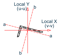
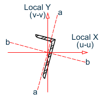
Angle sections are unsymmetric and when using BS 5950:2000 table 25, you must consider four axes: two principal, u-u and v-v and two geometric, a-a and b-b. The effective length for the v-v axis, Lvv, is taken as the LVV parameter or LY · KY, if not specified. The a-a and b-b axes are determined by which leg of the angle is fixed by the connection and should be specified using the LEG parameter, see section 5B.6 for more information on the LEG parameter. The effective length in the a-a axis is taken as LY · KY and the effective length in the b-b axis as LZ · KZ.
The following diagram shows the axes for angles which have been defined with either an ST or RA specification and is connected by its longer leg (i.e., a-a axis is parallel to the longer leg).