D8.B.4 Design Parameters
In the STAAD.Pro implementation of IS:800, you are allowed complete control of the design process through the use of design parameters. Available design parameters to be used in conjunction with IS:800 are listed in the table below along with their default values and applicable restrictions.
| Parameter Name | Default Value | Description |
|---|---|---|
| CODE | - |
Must be specified as INDIAN Design code to follow. See TR.48.1 Parameter Specifications. |
| BEAM | 1.0 |
0.0) design only for end moments and those at locations specified by the SECTION command. 1.0) calculate section forces at twelfth points along the beam, design at each intermediate location and report the critical location where ratio is maximum. |
|
CMY CMZ |
0.85 for sidesway and calculated for no sidesway | Cm value in local y & z axes |
| DFF | None(Mandatory for deflection check) | "Deflection Length" / Maxm.
allowable local deflection. See TR.40 Load Envelope for deflection checks using serviceability load envelopes. |
| DJ1 | Start Joint of member | Joint No. denoting starting point for calculation of "Deflection Length" (See Note 1) |
| DJ2 | End Joint of member | Joint No. denoting end point for calculation of "Deflection Length" (See Note 1) |
| DMAX | 100.0 cm. | Maximum allowable depth. |
| DMIN | 0.0 cm. | Minimum allowable depth. |
| FYLD |
250 MPa (36.25 ksi) |
Yield strength of steel. |
| KY | 1.0 | K value in local y-axis. Usually, this is minor axis. |
| KZ | 1.0 | K value in local z-axis. Usually, this is major axis. |
| LY | Member Length | Length in local y-axis to calculate slenderness ratio. |
| LZ | Member Length | Same as above except in local z-axis (major). |
| MAIN | 180 (Comp. Memb.) | Allowable Kl/r for slenderness calculations for compression members. |
| NSF | 1.0 | Net section factor for tension members. |
| PROFILE | - |
Used to search for the lightest section for the profile(s) specified for member selection. See TR.48.1 Parameter Specifications for details. |
| RATIO | 1.0 | Permissible ratio of the actual to allowable stresses. |
| SSY | 0.0 |
0.0) Sidesway in local y-axis. 1.0) No sidesway |
| SSZ | 0.0 | Same as above except in local z-axis. |
| TMAIN | 400 (Tension Memb) | Allowable Kl/r for slenderness calculations for tension members. |
| TRACK | 0.0 |
0.0) Suppress critical member stresses 1.0) Print all critical member stresses 2.0) Print expanded output. If there is deflection check it will also print the governing load case number for deflection check whenever critical condition for design is not DEFLECTION. |
| UNF | 1.0 | Unsupported length provided as a fraction of actual member length used for lateral-torsional buckling calculation. |
| UNL | Member Length | Unsupported length for calculating allowable bending stress. Used for the lateral-torsional buckling calculation. Value should be in the current units of length. |
Notes
-
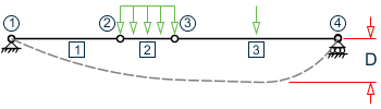
"Deflection Length" is defined as the length that is used for calculation of local deflections within a member. It may be noted that for most cases the "Deflection Length" will be equal to the length of the member. However, in some situations, the "Deflection Length" may be different. A straight line joining DJ1 and DJ2 is used as the reference line from which local deflections are measured.
For example, refer to the figure below where a beam has been modeled using four joints and three members. The "Deflection Length" for all three members will be equal to the total length of the beam in this case. The parameters DJ1 and DJ2 should be used to model this situation. Thus, for all three members here, DJ1 should be 1 and DJ2 should be 4. D = Maximum local deflection for members 1, 2, and 3.PARAMETERS DFF 300. ALL DJ1 1 ALL DJ2 4 ALL
- If DJ1 and DJ2 are not used, "Deflection Length" will default to the member length and local deflections will be measured from original member line.
- The above parameters may be used in conjunction with other available parameters for steel design.