Radial grid dialog
Used to generate construction lines in transformed radial coordinates. This is used to create circular type models where members are modeled as piece-wise linear straight line segments.
Opens when Radial is selected as the type of new grid or an existing radial grid is edited in a Snap Node/<entity> dialog.
| Setting | Description |
|---|---|
| Name | (Optional) Specify a name by which you can identify the grid in the Snap Node/<entity> dialog. |
| Plane | Used when the grid is to be placed in a global plane. Select the global plane in which the gridlines will lie. |
| Angle of Plane | Choose one of the three options (X-X, Y-Y, or Z-Z) and provide the angle of rotation (in degrees) of the grid plane about that axis. |
| Origin |
The (0,0) position on the grid in the grid coordinate system. Usually, the grid origin coincides with the structure origin. Type in the location of the origin of gridlines in global coordinate system, in the current length units, or click the |
| Construction Lines |
Start Angle, is the angle in degrees about the orthogonal axis to the plane from the axis first referred to in the definition of the plane. E.g. if the selected plane is X-Y, then the angle is measured about the Z axis (using the right hand rule) from the axis parallel to the X axis. Sweep is the angle in degrees measured from the start angle which is divided into the selected number of Bays, thus 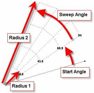
The nomenclature used for Radial grid construction lines |
 tool to change the location of the grid origin by graphically selecting a existing node.