M.To create a wide-flange user table section
To create a user-provided table section with a wide flange profile, including those with composite flanges or additional bottom plates, use the following procedure.
You may want to change the input dimensions prior to creating user provided table sections. Select to do so.
-
On the
Specification ribbon tab, select the
tool in the
Beam Profiles group.

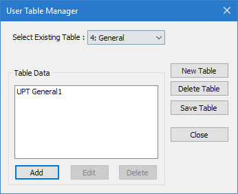
If no User Defined Table exists, you will be prompted to create one.
The User Table Manager dialog opens. - Click New Table. The New User Table dialog opens.
- the Select Section Type list, select WIDE FALNGE and then click OK. The dialog closes and the Table Data list in the User Table Manager dialog now has at least one entry.
- Click Add. The Wide Flange dialog opens.
- Type a Section Name.
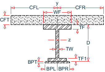
- 必須: Enter the following wide flange section parameters:
- (オプション) If the bottom flange has different dimensions, also specify:
- (オプション)
To specify a composite top flange:
- Check the Additional Composite Flange option. The Additional Composite Flange Specifications become active.
- Specify the following values:
- (オプション)
To specify an additional bottom flange plate:
- Check the Additional Bottom Steel Plate option. The Additional Bottom Steel Plate Specifications become active.
- Specify the following values:
-
Specify the section properties by either:
オプション 説明 To automatically have the program calculate the section properties… Click Calculate To manually specify the section properties… Type values for Cross Section Area (Ax), Inertia about local z (Iz), Inertia about local y (Iy), Torsional Constant (Ix), Shear Area in Y (Ay), and Shear Area in Z (Az) - Click OK.
- (オプション) Repeat steps 4 through 11 to add more wide flange sections.
- Click Close.
The section can now be added for use in the Properties - Whole Structure dialog by selecting it in the User Property Table dialog.
Refer to
EX. US-17 User-Provided Tables
and
EX. UK-17 User-Provided Tables
for examples of wide flange user-provided tables.