EX. US-17 User-Provided Tables
The usage of user-provided steel tables is illustrated in this example for the analysis and design of a plane frame. User-provided tables allow you to specify property data for sections not found in the built-in steel section tables.
This problem is installed with the program by default to C:\Users\Public\Public Documents\STAAD.Pro CONNECT Edition\Samples\Sample Models\US\US-17 User-Provided Tables.STD when you install the program.
Where:
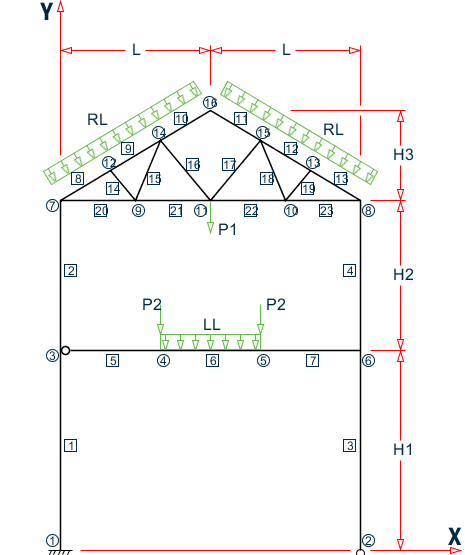
- L1 = 15 ft, L2 =20 ft
- P = 5.0 k
- w = 3.0 k/ft
Actual input is shown in bold lettering followed by explanation.
STAAD PLANE EXAMPLE FOR USER TABLE
Every input file has to start with the command STAAD. The PLANE command is used to designate the structure as a plane frame.
UNIT FT KIP
The UNIT command sets the length and force units to be used.
    JOINT COORDINATES
    1 0. 0. ; 2 30 0 ; 3 0 20 0 6 30 20 0
    7 0 35 ; 8 30 35 ; 9 7.5 35 ; 10 22.5 35.
    11 15 35 ; 12 5. 38. ; 13 25 38 ; 14 10 41 ; 15 20 41
    16 15 44
The above set of data is used to provide joint coordinates for the various joints of the structure. The Cartesian system is being used here. The data consists of the joint number followed by global X and Y coordinates. Note that for a space frame, the Z coordinate(s) need to be provided also.
    MEMBER INCIDENCES
    1 1 3 ; 2 3 7 ; 3 2 6 ; 4 6 8 ; 5 3 4
    6 4 5 ; 7 5 6 ; 8 7 12 ; 9 12 14
    10 14 16 ; 11 15 16 ; 12 13 15 ; 13 8 13
    14 9 12 ; 15 9 14 ; 16 11 14 ; 17 11 15
    18 10 15 ; 19 10 13 ; 20 7 9
    21 9 11 ; 22 10 11 ; 23 8 10
The above data set contains the member incidence information or the joint connectivity data for each member. This completes the geometry of the structure.
START USER TABLE
This command is utilized to set up a user-provided steel table. All user-provided steel tables must start with this command.
TABLE 1
Each table needs an unique numerical identification. The above command starts setting up Table no. 1. Up to twenty tables may be specified per run.
    UNIT INCH
    WIDE FLANGE
This command is used to specify the section-type as WIDE FLANGE in this table. Note that several section-types such as WIDE FLANGE, CHANNEL, ANGLE, TEE etc. are available for specification ( see TR.19 ユーザー鋼材テーブルの設定 ).
    WFL14X30
    8.85 13.84 .27 6.73 .385 291. 19.6 .38 4.0 4.1
    WFL21X62
    18.3 20.99 .4 8.24 .615 1330 57.5 1.83 0.84 7.0
    WFL14X109
    32. 14.32 .525 14.605 .86 1240 447 7.12 7.52 16.
The above data set is used to specify the properties of three wide flange sections. The data for each section consists of two parts. In the first line, the section-name is provided. You are allowed to provide any section name within twelve characters. The second line contains the section properties required for the particular section-type. Each section-type requires a certain number of data (area of cross-section, depth, moment of inertias etc.) provided in a certain order. For example, in this case, for wide flanges, ten different properties are required.
    TABLE 2
    ANGLES
    LANG25255
    2.5 2.5 .3125 .489 0 0
    LANG40404
    4 4 .25 .795 0 0
The above command and data lines set up another user provided table consisting of angle sections.
END
This command signifies the end of the user provided table data set. All user provided table related input must be terminated with this command.
    MEMBER PROPERTIES
    1 3 4 UPT 1 WFL14X109
    2 UPT 1 WFL14X30 ; 5 6 7 UPT 1 WFL21X62
    8 TO 13 UPT 1 WFL14X30
    14 TO 23 UPT 2 LANG40404
In the above command lines, the member properties are being assigned from the user provided tables created earlier. The word UPT signifies that the properties are from the user-provided table. This is followed by the table number and then the section name as specified in the use- provided table. The numbers 1 or 2 following the word UPT indicate the table from which section names are fetched.
    MEMBER TRUSS
    14 TO 23
The above command is used to designate members 14 to 23 as truss members.
    MEMBER RELEASE
    5 START MZ
The MEMBER RELEASE command is used to release the MZ moment at the start joint of member no. 5.
    DEFINE MATERIAL START
    ISOTROPIC STEEL
    E 29000
    POISSON 0.3
    DENSITY 283e-006
    ALPHA 6e-006
    DAMP 0.03
    TYPE STEEL
    STRENGTH FY 36 FU 58 RY 1.5 RT 1.2
    END DEFINE MATERIAL
    CONSTANT
    MATERIAL STEEL ALL
    BETA 90.0 MEMB 3 4
The DEFINE MATERIAL command is used to specify material properties and the CONSTANT is used to assign the material to all members.
UNIT FT
The length unit is reset to feet using this command.
UNIT FT
The length unit is reset to feet using this command.
    SUPPORT
    1 FIXED ; 2 PINNED
The above command set is used to designate supports. Here, joint 1 is designated as a fixed support and joint 2 is designated as a pinned support.
    LOADING 1 DEAD AND LIVE LOAD
    SELFWEIGHT Y -1.0
    JOINT LOAD
    4 5 FY -15. ; 11 FY -35.
    MEMB LOAD
    8 TO 13 UNI Y -0.9 ; 6 UNI GY -1.2
The above command set is used to specify the loadings on the structure. In this case, dead and live loads are provided through load case 1. It consists of selfweight, concentrated loads at joints 4, 5 and 11, and distributed loads on some members.
PERFORM ANALYSIS
This command instructs the program to execute the analysis at this point.
    PARAMETER
    CODE AISC UNIFIED
    BEAM 1.0 ALL
    NSF 0.85 ALL
    KY 1.2 MEMB 3 4
The above commands are used to specify parameters for steel design.
SELECT MEMBER 3 6 9 19
This command will perform selection of members per the AISC ASD steel design code. For each member, the member selection will be performed from the table that was originally used for the specification of the member property. In this case, the selection will be from the respective user tables from which the properties were initially assigned. It may be noted that properties may be provided (and selection may be performed) from built-in steel tables and user provided tables in the same data file.
FINISH
This command terminates a STAAD run.
Input File
STAAD PLANE EXAMPLE FOR USER TABLE
UNIT FT KIP
JOINT COORDINATES
1 0. 0. ; 2 30 0 ; 3 0 20 0 6 30 20 0
7 0 35 ; 8 30 35 ; 9 7.5 35 ; 10 22.5 35.
11 15 35 ; 12 5. 38. ; 13 25 38 ; 14 10 41 ; 15 20 41
16 15 44
MEMBER INCIDENCES
1 1 3 ; 2 3 7 ; 3 2 6 ; 4 6 8 ; 5 3 4
6 4 5 ; 7 5 6 ; 8 7 12 ; 9 12 14
10 14 16 ; 11 15 16 ; 12 13 15 ; 13 8 13
14 9 12 ; 15 9 14 ; 16 11 14 ; 17 11 15
18 10 15 ; 19 10 13 ; 20 7 9
21 9 11 ; 22 10 11 ; 23 8 10
UNIT INCH
START USER TABLE
TABLE 1
WIDE FLANGE
WFL14X30
8.85 13.84 .27 6.73 .385 291. 19.6 .38 4.0 4.1
WFL21X62
18.3 20.99 .4 8.24 .615 1330 57.5 1.83 0.84 7.0
WFL14X109
32. 14.32 .525 14.605 .86 1240 447 7.12 7.52 16.
TABLE 2
ANGLES
LANG25255
2.5 2.5 .3125 .489 0 0
LANG40404
4 4 .25 .795 0 0
END
MEMBER PROPERTIES
1 3 4 UPT 1 WFL14X109
2 UPT 1 WFL14X30 ; 5 6 7 UPT 1 WFL21X62
8 TO 13 UPT 1 WFL14X30
14 TO 23 UPT 2 LANG40404
*MEMBER TRUSS
*14 TO 23
MEMB RELEASE
5 START MZ
14 to 23 start MPY 0.99 MPZ 0.99
14 to 23 end MPY 0.99 MPZ 0.99
UNIT INCH
DEFINE MATERIAL START
ISOTROPIC STEEL
E 29000
POISSON 0.3
DENSITY 283e-006
ALPHA 6e-006
DAMP 0.03
TYPE STEEL
STRENGTH FY 36 FU 58 RY 1.5 RT 1.2
END DEFINE MATERIAL
CONSTANT
MATERIAL STEEL ALL
BETA 90.0 MEMB 3 4
UNIT FT
SUPPORT
1 FIXED ; 2 PINNED
LOADING 1 DEAD AND LIVE LOAD
SELFWEIGHT Y -1.0
JOINT LOAD
4 5 FY -15. ; 11 FY -35.
MEMB LOAD
8 TO 13 UNI Y -0.9 ; 6 UNI GY -1.2
PERFORM ANALYSIS
PARAMETER
CODE AISC UNIFIED
BEAM 1.0 ALL
NSF 0.85 ALL
KY 1.2 MEMB 3 4
SELECT MEMB 3 6 9 19
FINISH
STAAD Output File
                                                                  PAGE NO.    1
             ****************************************************
             *                                                  *
             *           STAAD.Pro CONNECT Edition              *
             *           Version  22.07.00.**                   *
             *           Proprietary Program of                 *
             *           Bentley Systems, Inc.                  *
             *           Date=    APR 19, 2021                  *
             *           Time=    17:27:59                      *
             *                                                  *
             *  Licensed to: Bentley Systems Inc                *
             ****************************************************
     1. STAAD PLANE EXAMPLE FOR USER TABLE
INPUT FILE: US-17 User-Provided Tables.STD
     2. UNIT FT KIP
     3. JOINT COORDINATES
     4. 1 0. 0. ; 2 30 0 ; 3 0 20 0 6 30 20 0
     5. 7 0 35 ; 8 30 35 ; 9 7.5 35 ; 10 22.5 35.
     6. 11 15 35 ; 12 5. 38. ; 13 25 38 ; 14 10 41 ; 15 20 41
     7. 16 15 44
     8. MEMBER INCIDENCES
     9. 1 1 3 ; 2 3 7 ; 3 2 6 ; 4 6 8 ; 5 3 4
    10. 6 4 5 ; 7 5 6 ; 8 7 12 ; 9 12 14
    11. 10 14 16 ; 11 15 16 ; 12 13 15 ; 13 8 13
    12. 14 9 12 ; 15 9 14 ; 16 11 14 ; 17 11 15
    13. 18 10 15 ; 19 10 13 ; 20 7 9
    14. 21 9 11 ; 22 10 11 ; 23 8 10
    15. UNIT INCH
    16. START USER TABLE
    17. TABLE 1
    18. WIDE FLANGE
    19. WFL14X30
    20. 8.85 13.84 .27 6.73 .385 291. 19.6 .38 4.0 4.1
    21. WFL21X62
    22. 18.3 20.99 .4 8.24 .615 1330 57.5 1.83 0.84 7.0
    23. WFL14X109
    24. 32. 14.32 .525 14.605 .86 1240 447 7.12 7.52 16.
    25. TABLE 2
    26. ANGLES
    27. LANG25255
    28. 2.5 2.5 .3125 .489 0 0
    29. LANG40404
    30. 4 4 .25 .795 0 0
    31. END
    32. MEMBER PROPERTIES
    33. 1 3 4 UPT 1 WFL14X109
    34. 2 UPT 1 WFL14X30 ; 5 6 7 UPT 1 WFL21X62
    35. 8 TO 13 UPT 1 WFL14X30
    36. 14 TO 23 UPT 2 LANG40404
    37. *MEMBER TRUSS
    38. *14 TO 23
      EXAMPLE FOR USER TABLE                                   -- PAGE NO.    2
    39. MEMB RELEASE
    40. 5 START MZ
    41. 14 TO 23 START MPY 0.99 MPZ 0.99
    42. 14 TO 23 END MPY 0.99 MPZ 0.99
    43. UNIT INCH
    44. DEFINE MATERIAL START
    45. ISOTROPIC STEEL
    46. E 29000
    47. POISSON 0.3
    48. DENSITY 283E-006
    49. ALPHA 6E-006
    50. DAMP 0.03
    51. TYPE STEEL
    52. STRENGTH FY 36 FU 58 RY 1.5 RT 1.2
    53. END DEFINE MATERIAL
    54. CONSTANT
    55. MATERIAL STEEL ALL
    56. BETA 90.0 MEMB 3 4
    57. UNIT FT
    58. SUPPORT
    59. 1 FIXED ; 2 PINNED
    60. LOADING 1 DEAD AND LIVE LOAD
    61. SELFWEIGHT Y -1.0
    62. JOINT LOAD
    63. 4 5 FY -15. ; 11 FY -35.
    64. MEMB LOAD
    65. 8 TO 13 UNI Y -0.9 ; 6 UNI GY -1.2
    66. PERFORM ANALYSIS
            P R O B L E M   S T A T I S T I C S
            -----------------------------------
     NUMBER OF JOINTS         16  NUMBER OF MEMBERS      23
     NUMBER OF PLATES          0  NUMBER OF SOLIDS        0
     NUMBER OF SURFACES        0  NUMBER OF SUPPORTS      2
           Using 64-bit analysis engine.
           SOLVER USED IS THE IN-CORE ADVANCED MATH SOLVER
   TOTAL      PRIMARY LOAD CASES =     1, TOTAL DEGREES OF FREEDOM =      43
   TOTAL LOAD COMBINATION  CASES =     0  SO FAR.
    67. PARAMETER
    68. CODE AISC UNIFIED
    69. BEAM 1.0 ALL
    70. NSF 0.85 ALL
    71. KY 1.2 MEMB 3 4
    72. SELECT MEMB 3 6 9 19
      EXAMPLE FOR USER TABLE                                   -- PAGE NO.    3
 PARAMETER 1
      EXAMPLE FOR USER TABLE                                   -- PAGE NO.    4
                       STAAD.PRO MEMBER SELECTION - AISC 360-16 LRFD (V1.2)
                     ********************************************************
 ALL UNITS ARE - KIP  FEET (UNLESS OTHERWISE Noted).
 ***NOTE : AISC 360-16 Design Statement for STAAD.Pro.
 *** AXIS CONVENTION ***:
 ========================
 The capacity results and intermediate results in the report follow the notations
 and axes labels as defined in the AISC 360-16 code.
 The analysis results are reported in STAAD.Pro axis convention and the AISC 360:16
 design results are reported in AISC 360-16 code axis convention.
   AISC Spec.      STAAD.Pro      Description
  ------------    -----------     -------------
       X               Z          Axis typically parallel to the sections principal major axis.
       Y               Y          Axis typically parallel to the sections principal minor axis.
       Z               X          Longitudinal axis perpendicular to the cross section.
 SECTION FORCES AXIS MAPPING: -
   AISC Spec.      STAAD.Pro      Description
  ------------    -----------     -------------
       Pz              FX         Axial force.
       Vy              FY         Shear force along minor axis.
       Vx              FZ         Shear force along major axis.
       Tz              MX         Torsional moment.
       My              MY         Bending moment about minor axis.
       Mx              MZ         Bending moment about major axis.
 *** DESIGN MESSAGES ***:
 =======================
    1. Section classification reported is for the cross section and loadcase that
       produced the worst case design ratio for flexure/compression Capacity results.
    2. Results for any Capacity/Check that is not relevant for a section/loadcase
       based on the code clause in AISC 360-16 will not be shown in the report.
    3. Bending results are reported as being �about� the relevant axis (X/Y), while
       the results for shear are reported as being for shear forces �along� the axis.
       E.g : Mx indicates bending about the X axis, while Vx indicates shear along
       the X axis.
 *** ABBREVIATIONS ***:
 ======================
    F-T-B = Flexural-Torsional Buckling
    L-T-B = Lateral-Torsional Buckling
    F-L-B = Flange Local Buckling
    W-L-B = Web Local Buckling
    L-L-B = Leg Local Buckling
    C-F-Y = Compression Flange Yielding
    T-F-Y = Tension Flange Yielding
      EXAMPLE FOR USER TABLE                                   -- PAGE NO.    5
                       STAAD.PRO MEMBER SELECTION - AISC 360-16 LRFD (V1.2)
                     ********************************************************
 ALL UNITS ARE - KIP  FEET (UNLESS OTHERWISE Noted).
 - Member :     3
|-----------------------------------------------------------------------------|
|  Member No:        3       Profile:  ST  WFL21X62            (UPT)          |
|  Status:        PASS       Ratio:         0.908       Loadcase:        1    |
|  Location:     20.00       Ref:      Eq.H1-1a                               |
|  Pz:       57.32     C     Vy:        0.000           Vx:     -1.784        |
|  Tz:       0.000           My:       -35.68           Mx:      0.000        |
|-----------------------------------------------------------------------------|
 - Member :     6
|-----------------------------------------------------------------------------|
|  Member No:        6       Profile:  ST  WFL21X62            (UPT)          |
|  Status:        PASS       Ratio:         0.534       Loadcase:        1    |
|  Location:      2.50       Ref:      Eq.H1-1b                               |
|  Pz:       3.813     T     Vy:       0.1573           Vx:      0.000        |
|  Tz:       0.000           My:        0.000           Mx:     -190.6        |
|-----------------------------------------------------------------------------|
 - Member :     9
|-----------------------------------------------------------------------------|
|  Member No:        9       Profile:  ST  WFL14X30            (UPT)          |
|  Status:        PASS       Ratio:         0.504       Loadcase:        1    |
|  Location:      5.83       Ref:      Eq.H1-3a(H1-1b)                        |
|  Pz:       37.86     C     Vy:        4.144           Vx:      0.000        |
|  Tz:       0.000           My:        0.000           Mx:     -54.45        |
|-----------------------------------------------------------------------------|
 - Member :    19
|-----------------------------------------------------------------------------|
|  Member No:       19       Profile:  ST  LANG25255           (UPT)          |
|  Status:        PASS       Ratio:         0.142       Loadcase:        1    |
|  Location:      1.95       Ref:      Eq.H2-1                                |
|  Pz:       3.970     C     Vy:       -.4173E-03       Vx:     -.4173E-03    |
|  Tz:       0.000           My:       -.6247E-02       Mx:     0.6247E-02    |
|-----------------------------------------------------------------------------|
    73. FINISH
   ****************************************************************************
   **WARNING** SOME MEMBER SIZES HAVE CHANGED SINCE LAST ANALYSIS.
               IN THE POST PROCESSOR, MEMBER QUERIES WILL USE THE LAST
               ANALYSIS FORCES WITH THE UPDATED MEMBER SIZES.
               TO CORRECT THIS INCONSISTENCY, PLEASE DO ONE MORE ANALYSIS.
               FROM THE UPPER MENU, PRESS RESULTS, UPDATE PROPERTIES, THEN
               FILE SAVE; THEN ANALYZE AGAIN WITHOUT THE GROUP OR SELECT
               COMMANDS.
   ****************************************************************************
             *********** END OF THE STAAD.Pro RUN ***********
               **** DATE= APR 19,2021   TIME= 17:27:59 ****
      EXAMPLE FOR USER TABLE                                   -- PAGE NO.    6
         ************************************************************
         *   For technical assistance on STAAD.Pro, please visit    *
         *   http://www.bentley.com/en/support/                     *
         *                                                          *
         *   Details about additional assistance from               *
         *   Bentley and Partners can be found at program menu      *
         *   Help->Technical Support                                *
         *                                                          *
         *           Copyright (c) Bentley Systems, Inc.            *
         *                http://www.bentley.com                    *
         ************************************************************