D2.B.8 Design Parameters
The design parameters outlined in the following table are used to control the design procedure. These parameters communicate design decisions from the engineer to the program and thus allow the engineer to control the design process to suit an application's specific needs. The design scope indicates whether design parameters are applicable for MEMBER Design, PMEMBER Design, or both.
The default parameter values have been selected such that they are frequently used numbers for conventional design. Depending on the particular design requirements, some or all of these parameter values may be changed to exactly model the physical structure.
| Parameter Name | Default Value | Design Scope | Description |
|---|---|---|---|
| CODE | - |
Must be specified as AUSTRALIAN to invoke design per AS 4100 - 1998. 準拠する設計コード。「TR.48.1 パラメータの設定」を参照してください。 |
|
| ALB | 2.0 |
Member section constant (refer cl. 6.3.3) If ALB is 2.0, it is automatically calculated based on TABLE 6.3.3(1), 6.3.3(2); otherwise the input value is used. |
|
| ALM | 0.0 |
Moment modification factor (refer cl. 5.6.1.1) If ALM is 0.0, it is automatically calculated based cl.5.6.1.1; otherwise the input value is used. |
|
| BEAM | 0.0 |
0.0 = design only for end moments and those at locations specified by SECTION command. 1.0 = Perform design for moments at twelfth points along the beam. |
|
| DFF | None (Mandatory for deflection check) | Analytical members only | Deflection Length/ Maximum Allowable local deflection. |
| DJ1 | Start Joint of member | Analytical members only | Joint No. denoting start point for calculation of deflection length |
| DJ2 | End Joint of member | Analytical members only | Joint No. denoting end point for calculation of deflection length |
| DMAX | 45.0 [in.] | Maximum allowable depth (Applicable for member selection) | |
| DMIN | 0.0 [in.] | Minimum required depth (Applicable for member selection) | |
| FU | 500.0 [MPa] | Ultimate strength of steel. | |
| FYLD | 250.0 [MPa] | Yield strength of steel. | |
| IST | 1 |
Steel type - 1 - SR, 2 - HR, 3 - CF, 4 - LW, 5 - HW |
|
| KT | 1.0 | Correction factor for distribution of forces (refer cl. 7.2) | |
| KY | 1.0 | K value for general column flexural buckling about the local Y-axis. Used to calculate slenderness ratio. | |
| KZ | 1.0 | K value for general column flexural buckling about the local Z-axis. Used to calculate slenderness ratio. | |
| LHT | 0 | Physical members only |
Load height position as described in Table 5.6.3(2) of AS 4100:1998
|
| LX | see desc. | Unbraced length between torsional restraints. The default is the distance between partial or full restraints which effectively prevent twist of the section about its centroid as per Sec. 8.4.4.1.2. | |
| LY | Member Length | Length for general column flexural buckling about the local Y-axis. Used to calculate slenderness ratio. | |
| LZ | Member Length | Length for general column flexural buckling about the local Z-axis. Used to calculate slenderness ratio. | |
| MAIN | 0.0 |
Slenderness checks for compression. Checks are not explicitly required per AS 4100. A value of either 0.0 or 1.0 suppresses the slenderness ratio check. Any value greater than 1.0 is used as the limit for slenderness in compression. |
|
| NSC | 1.0 |
Net section factor for compression members = An / Ag (refer cl. 6.2.1) |
|
| NSF | 1.0 | Net section factor for tension members. | |
| PBRACE | None | Physical members only | Refer to section 1B.11 for details on the PBRACE parameter. |
| PHI | 0.9 | Capacity reduction factor | |
| RATIO | 1.0 | Permissible ratio of actual load effect to the design strength. | |
| SGR | 0 |
Steel Grade. Refer to Note c below.
|
|
| SKL | 1.0 | A load height factor given in Table 5.6.3(2) | |
| SKR | 1.0 | A lateral rotation restraint factor given in Table 5.6.3(3) | |
| SKT | 1.0 | A twist restraint factor given in Table 5.6.3(1) | |
| TMAIN | 400 | Slenderness limit for tension. Checks are
not explicitly required per AS 4100.
Any value greater than 1.0 is used as the limit for slenderness in tension. |
|
| TRACK | 0 |
Output detail
|
|
| TSP | Member web depth | Spacing of the transverse stiffeners. | |
| UNB | Member Length | Unsupported length in bending compression of the bottom flange for calculating moment resistance. | |
| UNT | Member Length | Unsupported length in bending compression of the top flange for calculating moment resistance. |
D2.B.8.1 Notes
-
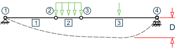
DFF, DJ1, and DJ2 – Deflection calculations
Compute Delta = SQRT((DX2 - DX1)2 + (DY2 - DY1)2 + (DZ2 - DZ1)2)
Compute Length = distance between DJ1 and DJ2 or, between start node and end node, as the case may be.
-
A straight line joining DJ1 and DJ2 is used as the reference line from which local deflections are measured.
-
If DJ1 and DJ2 are not used, "Deflection Length"will default to the member length and local deflections will be measured from original member line.
-
It is important to note that unless a DFF value is specified, STAAD.Pro will not perform a deflection check. This is in accordance with the fact that there is no default value for DFF.
-
-
LHT Parameter
If the shear force is constant within the segment, longitudinal position of the load is assumed to be at the segment end.
If there is any variation of the shear force and the load is acting downward determined from shear force variation and load height parameter indicates the load is acting on top flange (flange at the positive local y axis) and restraints at the end of the segment is not FU (FRU) or PU (PRU) Kl is assumed to be 1.4.
If there is any variation of the shear force and the load is acting upward determined from shear force variation and load height parameter indicates the load is acting on top flange (flange at the positive local y axis) and restraints at the end of the segment is not FU (FRU) or PU (PRU) Kl is assumed to be 1.0 as the load acting at the top flange is contributing to stabilize against local torsional buckling.
SGR Parameter
Rolled profiles typically use an AS/NZS 3679.1 grade (i.e., SGR 2 or SGR 3), hollow profiles typically use an AS/NZS 1163 grade (i.e., SGR 4 to SGR 6), welded profiles typically use an AS/NZS 3678 grade (i.e., SGR 7 to SGR 11), and pressure vessels typically use an AS/NZS 3597 grade (i.e., SGR 12 to SGR 14).When an explicit grade has not been specified or the option SGR 0 has been specified, the program determines the steel grade as follows:
Table 2. Default steel grades used for the SGR parameter Section Type Steel Grade Used WB, WC, Tee section cut from WB and WC, other welded and UPT sections AS 3678 300 UB, UC, Tee section cut from UB and UC, EA, UA and all UPT sections UB, UC, Tee section cut from UB and UC, EA, UA and all other rolled sections AS 3679.1 300 Pipe, Tube, CHS, RHS, SHS Pipe, Tube, CHS, RHS, SHS AS 1163 C250 Note: If a value for the FYLD parameter has been specified, then that value will be used. Otherwise, the SGR value will be used to determine the yield strength and tensile strength values for the steel. based on maximum thickness of the individual elements of the section. Only for shear capacity calculation web thickness is used. Similarly, Tensile Strength is determined either from FU parameter or from SGR parameter.
D2.B.8.2 Example
The following example uses the member design facility in STAAD.Pro. However, it is strongly recommended to use the Physical member design capabilities for AS 4100:
PARAMETER 1
CODE AUSTRALIAN
ALB 0.0 MEMBER ALL
ALM 1.13 MEMBER ALL
BEAM 1.0 MEMBER ALL
DFF 250.0 MEMBER ALL
DMAX 0.4 MEMBER ALL
DMIN 0.25 MEMBER ALL
FU 400.0 MEMBER ALL
FYLD 310.0 MEMBER ALL
IST 2.0 MEMBER ALL
KT 0.85 MEMBER ALL
KX 0.75 MEMBER ALL
KY 1.0 MEMBER ALL
LX 4.5 MEMBER ALL
LY 6.0 MEMBER ALL
MAIN 1.0 MEMBER ALL
NSC 0.9 MEMBER ALL
NSF 1.0 MEMBER ALL
PHI 0.9 MEMBER ALL
RATIO 0.9 MEMBER ALL
SGR 1.0 MEMBER ALL
SKT 1.0 MEMBER ALL
SKL 1.0 MEMBER ALL
SKR 1.0 MEMBER ALL
TRACK 2.0 MEMBER ALL
UNB 3.4 MEMBER ALL
UNT 6.8 MEMBER ALL
CHECK CODE MEMBER ALL