This standard covers building heights with less than 200 m
(666.67 ft). Wind actions are defined in two categories:
- Wu : ultimate limit states
- Ws: serviceability limit
states
In the following sections, AS/NZS 1170.2:2002 Structural
design actions - Wind actions manual is referred.
Site Wind Speed
(Vsit.β)
It is defined for the 8 cardinal directions (β) at the
reference height (z) above ground. The current implementation does not
calculate site wind speeds.
Design Wind Speed
(Vdes,θ)
The building orthogonal design wind speeds shall be taken
as the maximum cardinal direction site wind speed
Vsit,β
linearly interpolated between cardinal points within a sector ± 45 degrees to
the orthogonal direction being considered. For the ultimate limit state design,
Vdes,θ
shall not be less than 30 m/s. For leeward walls, side walls, and roofs, wind
speed shall be taken as the value at z=h, (h: the reference height and it shall
be taken as the average height of roof). For Windward wall, V might vary with
height > 25 m (~83.3 ft.)
Note that windward design wind speed is not explicitly
calculated by the program. Instead, the user is provided two choices: either a
constant wind speed is entered (so the wind over the height of the building is
assumed to be the same) or it is exclusively defined and read in from a user
defined file (so that one can consider variation of windward wind speed over
the height of the building). Further information is provided in coming
sections.
A constant Leeward wind speed is assumed in the current
implementation.
Design Wind
Pressure
The design wind pressure, in pascals, is calculated
according to the following equation:
| p =
0.5pair(Vdes,θ)2CfigCdyn
| 2.4(1) |
where
|
pair
| = | density of air (1.2
kg/m3) |
|
Vdes,θ
| = | building orthogonal design wind speed
(usually at θ=0. 90, 180, 270 degrees) |
|
Cfig
| = | aerodynamic shape factor (depending on
which part and geometry of structure |
|
Cdyn
| = | dynamic response factor ( =1 for non wind
sensitive structures)
- If
f > 1 Hz (T < 1.0
s), Cdyn = 1.0
- If
f < 0.2 Hz (T > 5
s), AZ/NZS 1170.2:2002 does not cover this type of structure
- If 0.2 < f < 1, (1 < T <
5), refer to Sections 6.2 & 6.3.
- Note that
Cdyn is calculated at a given height, z.
|
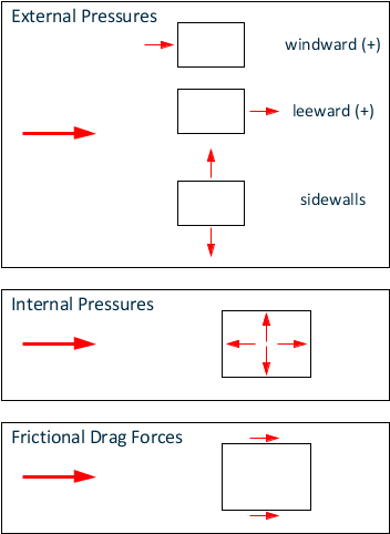
External Pressure
External Pressure for
enclosed buildings is
calculated according to the following equation:
| Cfig =
Cp,eKαKcKlKp
| 5.2(1) |
where
|
Cp,e
| = | external pressure coefficient (Section,
5.4.1 in the building code). It depends on which part of structure considered
(leeward, windward, upwind slope of roof, or downwind sloped of roof,
etc…) |
|
Kα
| = | area reduction factor (Section 5.4.2 in the
building code) |
|
Kc
| = | combination factor (Section 5.4.3). For
all structures, Kc cannot be
less than 0.8/Kα (i.e.,
Kc×
Kα≥ 0.8 |
|
Kl
| = | local pressure factor (Section 5.4.4).
There is also another correction applied to
Kl,
which is a reduction factor in the lee of the parapet. (Kl is 1.0 in
all cases except when determining the wind forces applied to cladding, their
fixings)
|
|
Kp
| = | reduction factor for porous cladding
(Section 5.4.5) |
Internal Pressure
Internal Pressure for
enclosed buildings is
calculated according to the following equation:
where
|
Cp,e
| = | internal pressure coefficient (Section,
5.3). Applies to inside of all structure, depending on openings and
permeability of walls. The height at which the wind speed is determined shall
be the average roof height (h).
|
|
Kc
| = | combination factor (Section
5.4.3) |
Friction Pressure
Friction Pressure for
enclosed buildings is
calculated according to the following equation:
where
|
Cf
| = | friction drag force coefficient. (it is
only applied where the ration d/H or d/b is greater than 4)
|
|
Kc
| = | combination factor (Section
5.4.3) |
Forces Derived from
Wind Pressures
where
|
F
| = | wind forces (in Newtons) |
|
pz
| = | design wind pressure in pascals (normal to
surface) at height z, calculated according to 2.4(1) in the building code.
|
|
Az
| = | reference area, in square meters, at
height z |
For enclosed buildings, internal pressures shall be taken
to act simultaneously with external pressures. The most severe combinations of
internal and external shall be selected for design.
Forces Derived from
Frictional Drag
where
|
fz
| = | design frictional distributed forces
parallel to the surface, calculated according to Section 2.4.2 (the equation
given in Section 2.4.2 is similar to Eq. 2.4(1) except different values of
Cfig
and Cdyn must be
used for frictional drag forces)
|
Forces and Moment
on Complete Structures
For rectangular enclosed buildings where the ratio d/h
or d/b is greater than 4, the total resultant force on a complete structure
shall include the frictional drag calculated in accordance with Section 5.5 in
the building code.
Implementation
Details
The following assumptions are enforced for the current
implementation:
- It is assumed that
building is effectively sealed and having non-opening windows. Hence, it is
further assumed that internal pressures cancel each other.
- It is assumed that
sidewalls external pressures cancel each other (note that internal pressure
also cancels out each other). See
Different
pressure types on buildings
.
- Frictional drag forces
are ignored (assumed that d/h or d/b is less than 4)
- Kl (local
pressure factor for cladding) is taken as 1
- Kp (reduction
factor for porosity) is taken as 1
- Ka (area
reduction factor for sidewalls) is taken as 1 (since external sidewalls
pressures are ignored (assumed to cancel each other)
- Kc
(combination factor) is taken as 1 (since only external pressures are applied
in the current implementation. This factor is used if external pressures are
applied with other types of pressures such as internal, side wall or upwind
roof, etc…)
- For buildings with height
less than 25 meters, the design wind speed (Vdes,θ) can be assumed
as constant over the height of the building. Otherwise, it varies with height.
Thus, the following options are provided:
- For leeward side wind
speed, it is always constant and measured at reference height
- For windward side
wind speed, two options are provided: Either
- It is assumed as
constant over the height of the building
- Or, it varies
with height. In this case, the engineer needs to provide this information
stored in a file (with an extension of
.WND) placed in the directory
"Tables." An example is given
below.
- Vdes,θ must be
defined for each orthogonal directions.
Different
pressure types on buildings
Example .WND
File
Also, the user has to provide values in consistent
units: SI (speed: m/s, height: m); Metric (speed: Km/s, height: m); or English
(speed: mph height: m);
// wind profile (height versus wind speed, height(m) vs Speed (m/s))
 0.0	35.0
10.		45.0
20.		60.0
30.		70.0
40.		80.0
Note: The first line
(beginning with
"//") is a comment and is ignored by the program.
Wind Action
Directions
Four orthogonal directions are considered for the load
case. It is assumed that building wind characteristics are the same for +X and
-X directions so that the same wind speed profile, windward\leeward exposure
constants and dynamic response factors (
Cdyn) are used
for +X and -X. This is also true for +Y and -Y.
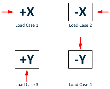
Orthogonal
load cases