Slenderness
You can choose to consider slenderness by selecting the option in the Criteria Analysis dialog of the Concrete Analysis mode (see the Concrete Analysis manual). Where the slenderness option is selected, the program considers the sidesway, effective length factor, and unbraced column length, to calculate the slenderness moment magnification factor for each design data point.
Sidesway
For each column, you can set global criteria or directly assign a sway (unbraced) or non-sway (braced) designation to each column axis in the Analysis Mode (See RAM Concrete Analysis Manual). This sway setting is used to determine if the program will consider moment magnification per ACI 10.12 for non-sway frames or per ACI 10.13 for sway frames.
K-Factor
For each column, you can set global criteria or directly assign a K-Factor designation to each column axis in the Analysis Mode (See RAM Concrete Analysis Manual). In both cases, you can specify either a specific K value, or select to use the nomograph to calculate the K-Factor for a particular axis.
| k = 0.7 + 0.05(ΨA + ΨB) ≤ 1.0 | ACI R10.12.1 (A) |
| k = 0.85 + 0.05Ψmin ≤ 1.0 | ACI R10.12.1 (B) |
| = |
The full centerline member distances are used when calculating effective length (per ACI definition of length in the nomograph footnote).
Some issues to be aware of related to how the program calculates Ψ and effective length factor K are as follows:
ψ is limited to 10.0 for columns when there are no beams framing in, or when only pinned end beams are framing in; this limits K to a value of 3.0, rather than the theoretical value of infinity. Note that gravity concrete beams with beam line numbers assigned will be assumed fixed to the supporting columns for the purposes of these calculations. Gravity concrete beams without beam line numbers will be assumed pinned for K factor calculation.
Ψ is limited to 1.0 at the bottom of the column if it is assumed fixed at its base.
The cracked section factors are applied to all section properties per 10.12.1 for the calculation of Ψ.
Columns that are pinned top and bottom are given K-factors of 1.0.
Beams that frame into a column axis at an angle larger than 80 degrees are not considered when calculating Ψ for that axis of the column.
Moment Magnification
To calculate the appropriate moment magnification factor (if any) to apply to a specific design data point the following logic is implemented by the program, all code references are to ACI 318-02:
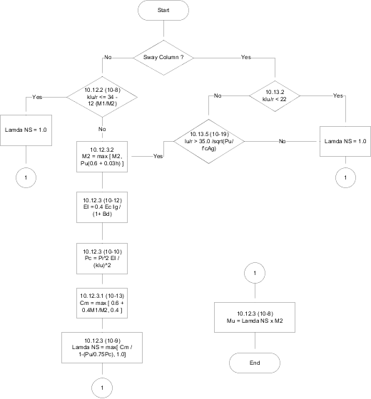
βd (For Non-Sway frames) = Ratio of factored axial dead load force to the full axial force in the column for the specific design data point.
βd (For Sway frames) = 0.0 (assumed no sustained lateral force is part of the load combination).
To ensure the largest moment magnification factor per ACI 10.12.3 (10-8) δns is calculated, the column design points are pattern loaded (assumed to occur in pairs) as shown below. This ensures that the column is in single curvature for the calculation of C m for ACI 10.12.3.1, so as to produce the largest C m value. It also produces the lowest limit to require a slenderness check for non-sway frames per ACI 10.12.2.
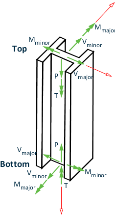
The sign convention for column forces is illustrated in the figure below.
The following patterns of design points (see Design Forces and the Concrete Analysis Manual for an explanation of design points in a skip loaded column) are applied simultaneously to produce the largest Cm value (single curvature for ACI 10.12.3.1) and the lowest slenderness limit for non-sway frames (ACI 10.12.2).