Design Forces
The user can generate or create custom load combinations as described in the Load Combination Generator Manual. These load combinations are then used to calculate the design points as described below.
Axial, Moments, and Torsion
As observed in Gravity Forces and Lateral Forces , there are two sets of forces computed for each of the dead, roof live, and all lateral load cases (one top and one bottom set of column forces for each). For every load combination that only includes dead, roof live and/or lateral load cases, two design points will be generated.
For example, consider the column gravity (from RAM Concrete Analysis orRAM Frame) and lateral forces (from RAM Frame) shown in the preceding table.
| Setting | Description |
|---|---|
| Data Point 1 (top) |
Axial = 1.0 x 10 + 1.2 x 30 = 46 M major = 1.0 x 100 + 1.2 x 120 = 244 M minor = 1.0 x -30 + 1.2 x 5 = -24 Torsion = 1.0 x 5 + 1.2 x 1 = 6.2 |
| Data Point 2 (bottom) |
Axial = Same as top = 46 M major = 1.0 x -40 + 1.2 x -60 = -112 M minor = 1.0 x 30 + 1.2 x -10 = 18 Torsion = Same as top = 6.2 |
For skip loaded floor live loads, as observed in Gravity Forces , there are eight sets of forces computed for floor live load (four top and four bottom sets of forces). For every load combination that includes floor live load the program produces eight sets of design forces, combined in load combinations the same way as described above. The program also generates an additional eight design points by using the total axial force (from all beams loaded) in each of the skip load cases (cases i-viii in Gravity Forces ). This ensures that ACI Section 8.8.1, which mandates that "Columns shall be designed to resist the axial forces from factored loads on floors or roof and the maximum moment from factored loads on a single adjacent span of the floor or roof under consideration." This results in 16 distinct design points for each load combination that has a floor live load as one of its cases.
For sway columns the lateral column moments produced by RAM Frame when P-Delta is considered are considered to be the magnified sway moments per ACI 10.13.4.
The design moments described in this section may be further amplified if the column is slender as described in Section 4.3 for ACI.
Shear
The same methodology as described above is used in determining the design shear force in load combinations. However, where eight force sets are calculated as described in Gravity Forces , the program needs to know which moments are assumed to occur simultaneously at each end of the column. RAM Concrete Column will calculate the column shear based on the direction of moments at each end of the column that produces the largest gravity column shear. As illustrated in the following figure , the column pattern loads that produce the maximum shear (Case 1) are used.
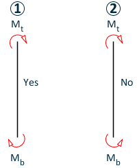
The following pattern of design points (see Gravity Forces and the RAM Concrete Analysis manual for an explanation of design points in a skip loaded column) are applied simultaneously to produce the largest shear value: