Limiting Neutral Axis Calculation
ACI 318-11, 21.9.6.2 states that compression zones shall be reinforced with special boundary elements when:
| ACI (21-8) |
| = | ||
| = | ||
| = | ||
| = | ||
| = | ||
| = |
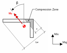
RAM calculates the parameter lw as the overall horizontal dimension of the wall panel or core as measured in the direction of loading for a specific load combination.
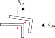
The parameter δ e is measured as the horizontal displacement at the centroid of the top of the Wall Design Group, minus the displacement at the centroid of the Section Cut for the respective load combination. The value is formulated from the lateral displacements solved for in RAM Frame and can be verified from the Load Combinations mode in RAM Frame. The displacements for each load case are combined according to the respective load combination under consideration in the RAM Concrete Wall module. The parameter hw is taken as the vertical distance from the bottom of the story at which the Section Cut is located to the overall top of the Wall Design Group.
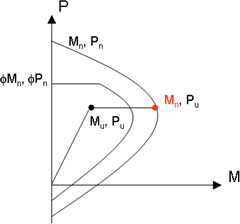
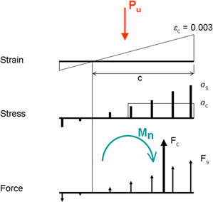
The neutral axis calculation uses the factored axial load Pu that acts on the entire Section Cut. From this, the nominal moment strength coincident with the applied axial load is determined along with the corresponding neutral axis depth (see the following pair of figures).