CONTROL4:
Purpose
Control 4 consists of two selection buttons; one to indicate the use of program calculated values and one to indicate the use of values entered by a user.
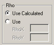
Control 4 is a special control that is used in the RAM Structural System to apply the Redundancy Factor, Rho, to the seismic load in combinations. As currently implemented, the Use Calculated option will always assign the calculated value of Rho to the variable. This control can also be used, however, for other purposes if the Use Calculated option is not used. It is useful when the value of the load factor is dependent upon the direction of the load case.
Format
CONTROL4: T/F, LoadCaseSymbol, ,Text
V40, Text1, Text2, MinV1, MaxV1, DefV1, MinV2, MaxV2, DefV2
DEFAULT: CALC/USER/USE_ONLY
The Control 4 line begins with CONTROL4: followed by either T or F. An F (False) indicates that the control is not used, and no additional information is necessary. In this case, the Control 4 options will not appear in the Load Combination dialog box.
A T (True) indicates that the control is to be used, and the Control 4 line must contain the additional information LoadCaseSymbol, a blank, and Text. The items must be separated by commas as shown and the blank must be included (it is not currently used but is to provide for a future expansion of the capability of the control).
LoadCaseSymbol is a Load Case symbol as given in Load Case Symbols Load cases of this type must have been Analyzed in order for this control to be available. If LoadCaseSymbol is left blank, the control will always be available (unless the control flag was set to F). Text is the text that will appear above the option.
- Text1 is a text string that will be associated with the first of two edit boxes. The text string may include blanks and may have up to 4 characters.
- Text2 is a text string that will be associated with the second edit box.
- MinV1 is the minimum allowable value for that variable as specified in the first edit box; if the user specifies a value less than that, a Warning will be given by the program.
- MaxV1 is the maximum allowable value for that variable as specified in the first edit box; if the user specifies a value greater than that, a Warning will be given by the program.
- DefV1 is the default value that will initially appear in the edit box, but which the user can change. For convenience it should be given the value that is most likely to be specified.
- MinV2 , MaxV2 and DefV2 are the minimum, maximum and default values, respectively, associated with the second edit box.
The value assigned to the variable V40 is dependent upon the direction of the load case to which it is assigned. If the load case acts in the global X-axis direction, the value assigned to V40 is the value specified in the first edit box. If the load case acts in the global Y-axis direction, the value assigned to V40 is the value specified in the second edit box. If the load case acts at an angle or has components in both the X- and Y-axis directions, the greater of the values specified in the two edit boxes will be assigned to V40 .
The final line must begin with DEFAULT: followed by either CALC , USER or USE_ONLY . If CALC is specified, the default selection will be the "Use Calculated" option. If USER is specified, the default selection will be the "Use" option. USE_ONLY is a special value which should be specified if Control 4 is used for anything other than Rho; it causes the Use Calculated option to be disabled.