Analysis
Select to display the analysis criteria dialog box. Analysis criteria allow you control over the analytical model that is created, as well as the number of load cases that are generated. These criteria also control the quantity of forces that are extracted for the design modes as described below. For detailed technical information refer to the technical chapter of this manual.
| Setting | Description | ||||||||||||||||||||||||||||||||||||||||
|---|---|---|---|---|---|---|---|---|---|---|---|---|---|---|---|---|---|---|---|---|---|---|---|---|---|---|---|---|---|---|---|---|---|---|---|---|---|---|---|---|---|
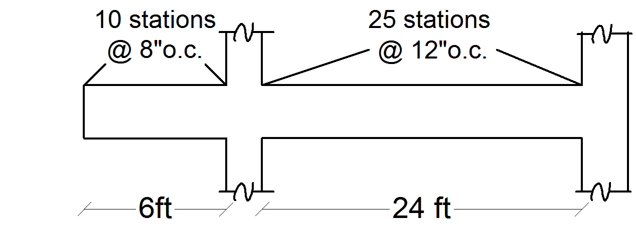
| Analysis Stations | An analysis station is a single location along the length of a beam at which forces are calculated for consideration in the beam design mode (see Section 3.5.2). You can control the number of stations along each concrete beam. These stations are also the locations at which the design checks will be performed. The larger the number of stations the more forces are saved and checked in design for each beam. The number of stations on any span will be based on the controlling of the two criteria in this frame (see example below). For beams spanning between columns, the stations are always calculated based on the clear length (face-to-face of columns). For beams supported on girders the stations are calculated based in the center-to-center span length. Minimum number of stations per beam : Specify the minimum number of stations per span of each physical beam. For a cantilever beam the cantilever and back-span are considered separate spans for the purposes of these criteria. Maximum spacing between stations : Specify the maximum spacing you want between any two adjacent stations. Example Minimum number of stations per beam = 10 Maximum spacing between adjacent stations = 12" (250mm) Resulting number of stations on the cantilever Resulting number of stations on the back-span For the cantilever span the minimum number of stations controls the number of stations, for the back-span the maximum spacing criteria controls the number of stations. The number of stations will have an effect on the force diagrams produced as illustrated in figure below. |
||||||||||||||||||||||||||||||||||||||||
| Rigid End Zones | Whether or not to consider the effects of rigid end zones is declared in the Rigid End Zone box. The engineer may choose to ignore these effects by clicking the Ignore Effects option button. To include the effects, click the Include Effects option and either enter a percent reduction (between 0 and 100%) in the edit box or accept the default value of 0%. The percentage provided reduces the rigid end zone from the full length (full length is considered to be half the column dimension in the direction of the beam). See the Chapter 3 for more information on Rigid End Zones. | ||||||||||||||||||||||||||||||||||||||||
| Beam Torsion Stiffness | There are several references that indicate that concrete members will typically exhibit significantly less torsional stiffness than might be calculated using the full cross sectional properties (see Material Properties For more information on the references). In RAM Concrete the torsional stiffness J is calculated based on the dimensions of the web of the beam (not including flange overhangs). The torsional stiffness of the beam can then be reduced on a beam-by-beam basis based on the torsion cracked factor assigned to the member in the RAM Modeler OR the engineer can select to reduce the torsion stiffness for all concrete beams by the magnitude specified in this dialog. Note if using the value specified in this dialog the gross member torsion stiffness will be multiplied by (1.0 - Specified reduction %) to determine the final beam torsion stiffness. Note that for all other stiffness properties (flexure and axial stiffness) the cracked factor assigned to the both beams and columns in the Modeler are considered to reduce the associated stiffness value. |
||||||||||||||||||||||||||||||||||||||||
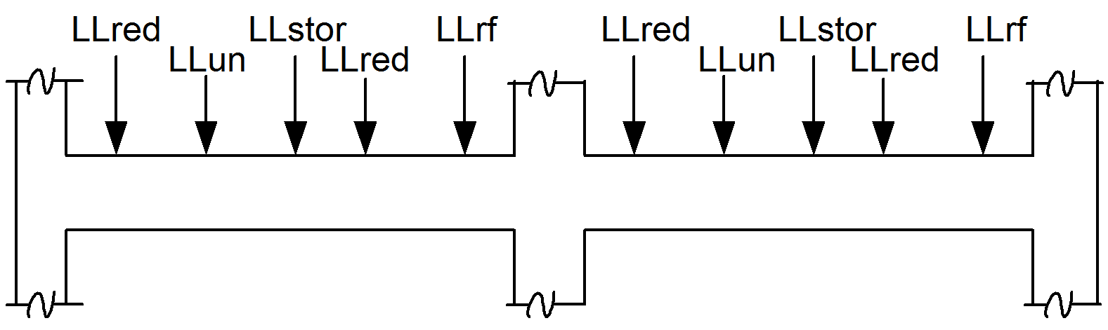
| Loading | The loading criteria directly relates to the number of load cases that are generated by the program and applied to the analysis of each story. Note that the larger the number of load cases the longer the analysis time. Skip load the live load on beam line beams : Select this option to skip load the live load on beams that have assigned beam line numbers. (See Assign Beam Lines for a description of beam lines.) When selected, the program creates one load case per unique live load type (storage, reducible, un-reducible and partition) per beam span. Dead load and Roof live load are not skip-loaded. Also, for beam lines in the two way regions only live loads applied directly to the beams is considered for skip loads. Skip load the live load on non-beam line beams : Select this option to skip load the live load on beams that do not have beam line numbers. This option can be selected to obtain skip loaded concrete column forces where the concrete column supports beams without beam line numbers. Selecting this option could increase the number of load cases generated (and hence increase the analysis time). Consider Live Load Reduction : Select this option to have the live load reduction applied to the forces calculated from each span. The program calculates a live load reduction factor for each live load type (roof, reducible and storage) on each member (beam and column). Refer to the RAM Steel manual for a description of the different load types (reducible, unreducible, storage, roof and partition). The analysis is performed for each live load type independently (i.e. different load cases) if this option is selected. This is to allow the program to reduce the resulting member forces by its corresponding live load reduction value before combining. Where no live load reduction is to be considered all live load types on a beam span can be applied in a single load case for analysis, and no reduction is made to the resulting forces. Refer to the technical chapter for details on how live load reduction is calculated. Consider Load Polygons as Load Cases on Two-way deck (for pattern loading) : Select this option to skip-load the surface live loads on two-way regions. When selected, the program creates one load case per unique live load type (storage, reducible and un-reducible) per surface load polygon. Dead load and Roof live load are not skip-loaded. Also, if there are any partition surface live loads they are treated similar to un-reducible live load by the program and they show up in un-reducible live load component. Example All loads are live loads and beam self wt (dead load) is also applied. The table below shows the number of load cases that will be generated based on the user-selected skip load and live load reduction criteria. Number of load cases generated (based on the user-selected criteria)
|
||||||||||||||||||||||||||||||||||||||||
| Analysis Constraints | Several options are available to control finite element model that is created in the RAM Concrete Gravity Analysis.
|
||||||||||||||||||||||||||||||||||||||||
| Hanger Column Load Iteration |
Convergence Tolerance (% Change)
This convergence tolerance value is used to determine the termination of hanging column load iteration. The load iteration is performed to achieve convergence in the load coming through hanging column from level below to the level above. The smaller this tolerance gets the program may take more number of iterations to converge. The default value of this tolerance is set to 5%. |
||||||||||||||||||||||||||||||||||||||||
| Speed |
|
||||||||||||||||||||||||||||||||||||||||
| Design |
|
||||||||||||||||||||||||||||||||||||||||
| Solver Type | Several types of solvers are offered in the program. Basically they are categorized in two flavors: in-core and out-of-core solvers. With in-core solvers, the global building stiffness matrix is assembled, stored and solved in the physical memory (RAM) of the computer. As long as there is enough memory available for the solution of the models, this choice always gives the best performance/solution time. However, for very large models, the in-core solver might run into out-of-memory errors. If this is the case, it is suggested to switch to out-of-core direct solver. With the out-of-core solver, the program assembles stores and solves building stiffness matrix using files that are stored on the hard-drive of the computer. Thus, it involves repeated access to the hard drive, which may substantially increase analysis time. It is always recommended that models should first be run with the in-core solvers and if an out-of-memory error is detected, then the out-of-core should be used. Also, one should note that the results remain unchanged whatever solver is used in the analysis.
|
||||||||||||||||||||||||||||||||||||||||
| Analytical Model |
|