Beam Gravity Forces
Each concrete beam, with an assigned beam line number, is divided into multiple stations. The program will also automatically add stations at each point load, at the face of columns, at any location where any other member frames into the physical beam. A station refers to a single point along the length of a beam where beam forces will be computed and considered in the design. Note that beam forces are always given up to the face of supports (where beams span into columns) or up to the end where they span into other beams or walls. The user can control the quantity of stations by selecting the appropriate option in the Analysis Criteria dialog box (see Section 2.5.2). RAM Concrete calculates beam design forces for dead load, live load and roof live load independently.
For live load, ACI R8.9 reads as follows, "The engineer is expected to establish the most demanding set of design forces by investigating the effects of live load placed in various critical patterns." RAM Concrete allows the engineer to implement this requirement by providing the option to skip load the live load (see Section 2.5.2). This is similar to the intent of BS8110 3.2.1.2.2.
Where skip loading is selected for beam line or non-beam line beams, the following procedure for calculating live load beam forces is implemented. For each live load case (see Section 3.3.10) of type reducible, unreducible (includes partition) or storage (see Sections 3.3.1) the program will compute the shear, moment and torsion at each station along the length of the beam. The program will then multiply each of these forces by the appropriate member live load reduction factor (see Section 3.3.9) and sum same-sign forces for each station. In other words, the program adds positive values to each other at each station and negative values to each other at each station. Thus, only when a specific load case increases the force at a station will it be considered. When completed the program has two curves for each beam for the floor live load case, a positive and a negative curve. These curves represent the largest force (positive and negative); from the worst skip loaded condition that can exist at any station along the beam length. This process is illustrated graphically below.
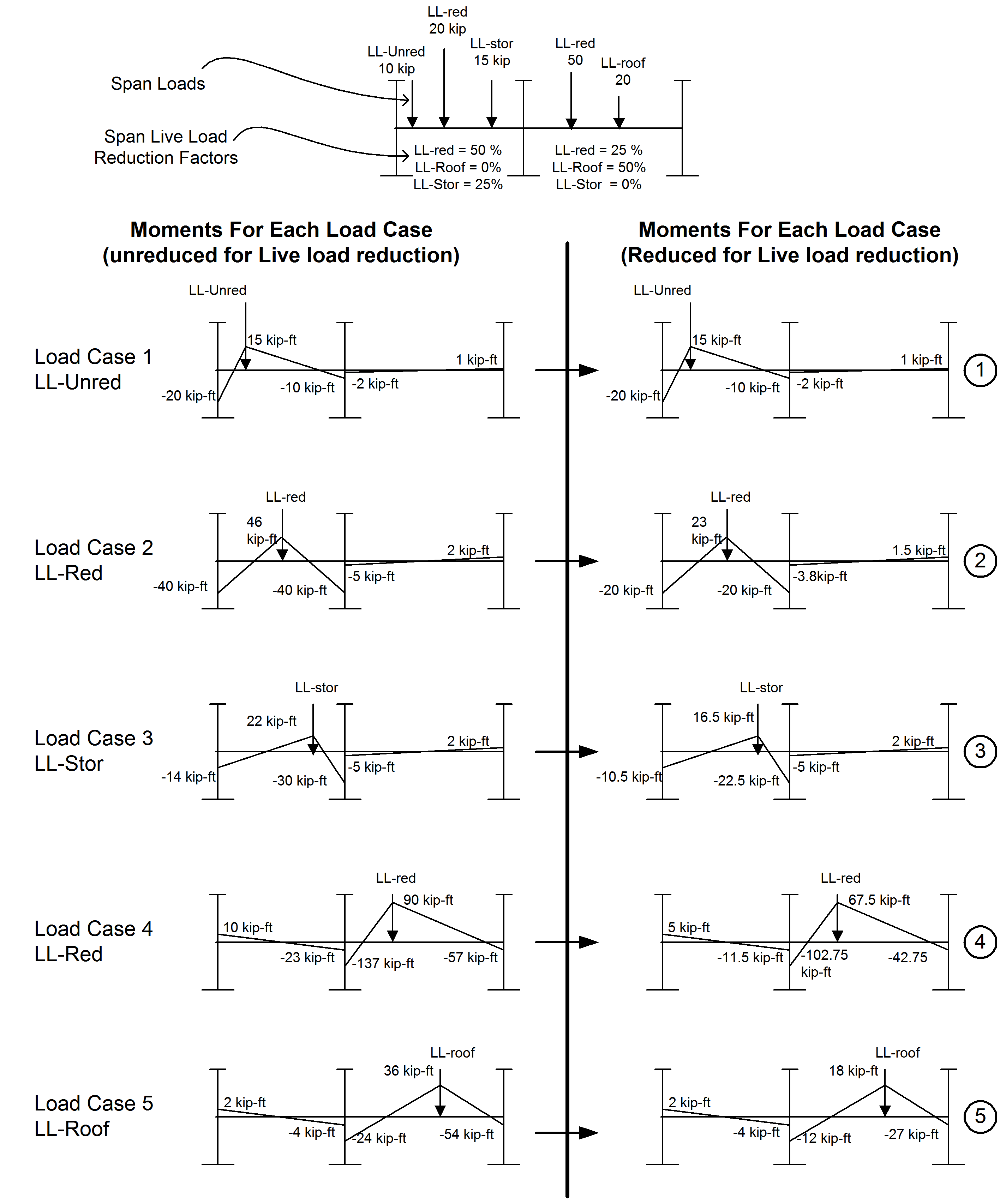
Forces from floor live load cases are added at each station where their effect increases the positive or negative force at the station. For roof live load the forces are added together irrespective of sign to produce a single curve.
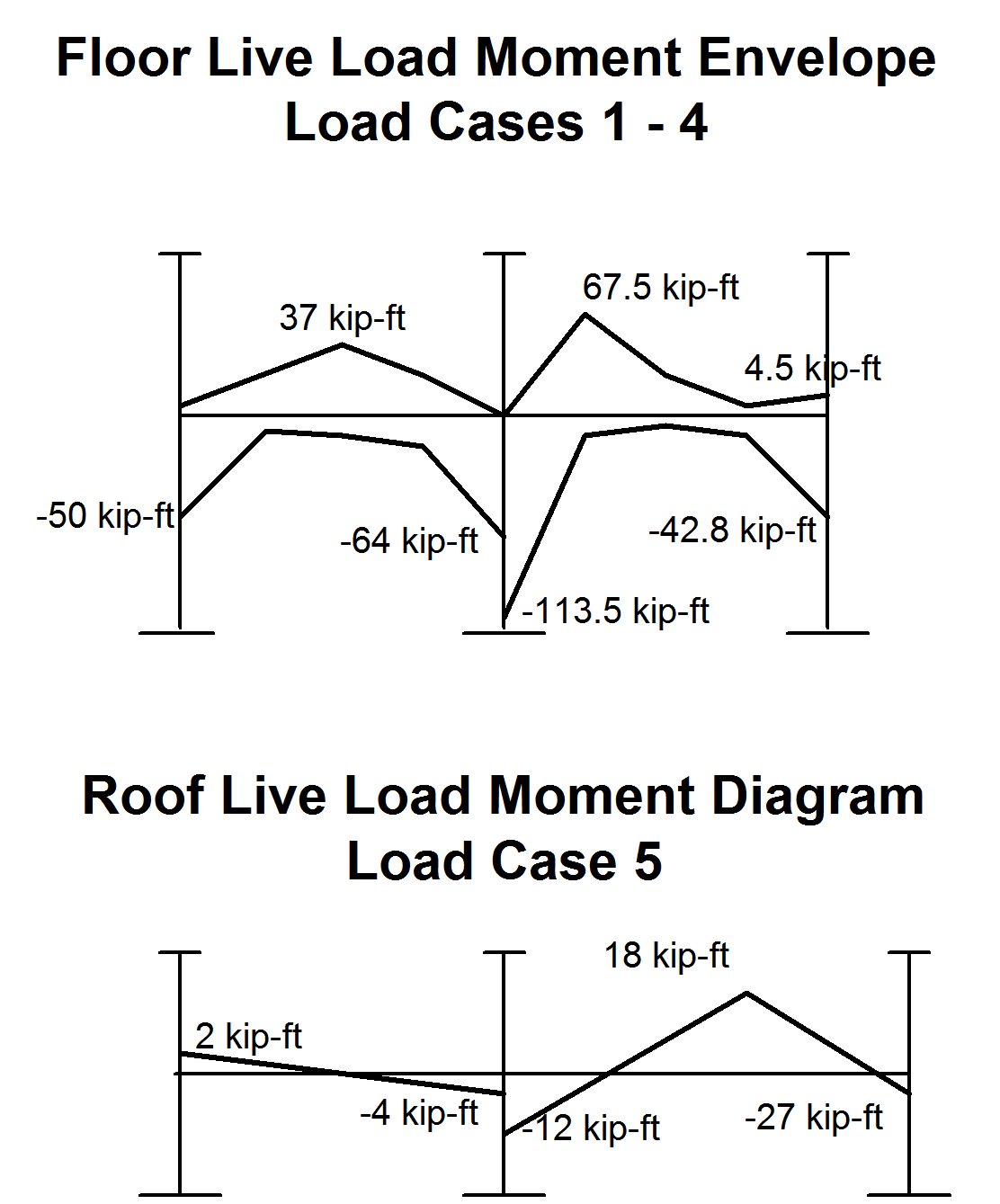
For dead load and roof live load no skip loading is performed and the forces produced are due to all dead or roof live load applied simultaneously. There is only a single curve of forces for these load cases. There is no moment redistribution implemented in RAM Concrete. Note that the user will find that in most cases the reduction in the required moment capacity is not significant enough to justify the effort of moment redistribution.
All the computed beam live load envelope and dead and roof load force diagrams can be viewed in the Beam Line Force Envelope report (see Section 5.7)