Effects of Sloping Framing
Beams
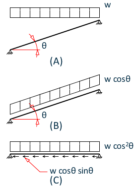
In the Modeler, Live Load Surface and Line loads that are applied to sloping framing areas should be assigned magnitudes equivalent to their projected area loads (for Surface loads) and projected length loads (for Line loads); Live Loads specified in most building codes are already specified as projected area loads, so no modification is necessary. Dead Loads should be input as the actual loads, based on the actual weights; the program will account for the effects of sloping. The figure below shows how beam Live Loads are dealt with in the RAM Structural System. Figure (A) shows the load as applied by the user. The load is then transformed to calculate the load per unit length along the member, as shown in Figure (C). The load is transformed again to calculate both the perpendicular and axial components along the member, as shown in Figure (C). In RAM Concrete both the perpendicular and axial components are considered in the analysis.
Columns
Columns too can be sloped in the Modeler. For a sloped column, the column self weight for the column length will be applied as a unit point load to the top of the column, and no externally applied loads are considered acting along the length of the column. Note that only moments at the ends of the column are considered in the design module and columns with large(r) moment that occur along the length of a member should be designed outside of this application.