Design Approach
For all valid joints (refer to the section on limitations for the definition of a valid joint) the program will calculate the capacity of the column web and flanges to resist the applied forces. For all codes the panel zone shear checks are performed before any of the other required joint checks. RAM Frame calculates the shear in the panel zone as the net sum of the shear from the column above, the shear applied to the joint from the story (through the diaphragm), the axial load in the beams (divided between the beam flanges) and the shear due to beam moments. As illustrated in the figure below the story shear applied to the joint is assumed to be the net difference of the shear in the column above the joint, the axial load in the beams framing into the joint, and the column shear directly below the joint. Note that the angle of the column above the joint, and the beams framing into the joint, is considered when calculating Vcol above, PA and PB.
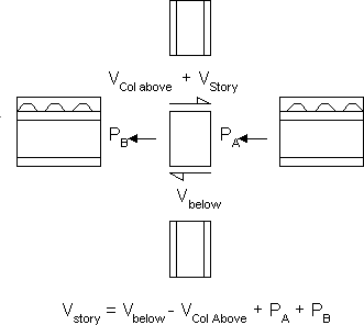
When calculating the design panel zone shear the program assumes that this story shear is applied above the joint. In the case where a valid joint is not connected to the diaphragm there should be no story shear applied to the joint. An exception to this is the case where a brace frames into the joint from above.
The panel zone forces are calculated as shown in the figure below. Dashed arrows represent the moments and axial loads applied to the joint by the beams. To determine the panel zone shear, these moments and axial loads are resolved into concentrated flange forces as shown by the solid arrows.
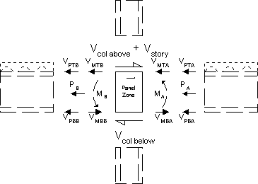
In this figure the applied beam moments (MA and MB) are resolved into a couple by dividing by the beam depth (VMTA = VMBA = MA/Beam depth [between mid heights of flanges]). The story shear is assumed applied above the panel zone. The axial load in the beams is applied to the joint through the beam flanges based on their areas. VPTA is therefore calculated as PA x Area of Top flange of Beam A / Total flange area for beam on side A. The panel zone shear for the forces shown in this figure (all forces shown are positive in magnitude) is calculated as:
Panel zone shear = Vcol above + Vstory - VPTB -VPTA - VMTB - VMTA.
The beam flange-to-column-flange force used for the other joint checks is taken as:
Concentrated top flange force side B of joint = VPTB + VMTB.
The other beam flange-to-column-flange forces are calculated in the same manner.
In the event that the ability of the column web to resist the applied shear is exceeded, then an appropriate web plate (doubler) will be designed. RAM Frame will only provide a web plate where the panel zone shear capacity of the column is exceeded by more than 1%. If a web plate is required, then where the capacity of a column’s flanges and web (including the contribution of the web plate) is exceeded for any of the concentrated force checks, RAM will attempt to increase the thickness of the web plate to increase the columns capacity. If an adequate web plate cannot be designed, then a stiffener will be used and the web plate will once again only be sized for the panel zone shear. Where no web plate is required for panel zone shear check, but the capacity of the column flanges and web is exceeded for any of the concentrated force checks, RAM will provide a stiffener to meet the code requirements. The design of the web plate and stiffeners at a joint is based on the criteria provided by the engineer through the dialog displayed by invoking the Criteria-Joints menu item.