Design Forces
The forces applied at the beam-column connection can be determined from either the design load forces or from the bending capacities of the members at the joints.
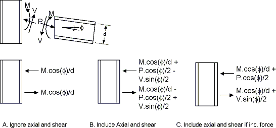
When design load forces are selected to be used, the program will determine the largest panel-zone shear, as well as the largest concentrated force at each beam flange, from all load combinations. The forces are calculated as illustrated in the figure. The engineer also has the option of indicating which method the program uses to apply beam axial load to the joint. The ramifications of each of the three available options on the joint design forces are indicated in the figure below. Case A illustrates the flange forces when the user has indicated to use the design moment ignoring the axial load. Case B is where the engineer is using the design moment considering the axial load and case C is where the engineer only considers axial load if it increases the force on the column.
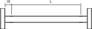
If the plastic capacity of the section is specified to be used, then the engineer must specify an appropriate overstrength factor. The plastic capacity of the member is calculated as the product of the members plastic modulus, yield strength and the overstrength factor. The force applied to the column flange is thus the member plastic capacity divided by the distance between the center of the beam flanges. In the event that the member has a reduced beam section specified. The moment at the face of the column used to calculate the joint forces is taken as Mpr + Vp*Xf. Where, as illustrated in the figure below:
Mpr is the member plastic capacity at the reduced beam section, L is the distance between reduced beam sections, Xf is distance from the center of the reduced beam section to the face of the column, and Vp is taken as 2 Mpr / L.