NBCC 2005 Wind
| Setting | Description | |||||||||||||||||||||||||||||||||||||||||||||
|---|---|---|---|---|---|---|---|---|---|---|---|---|---|---|---|---|---|---|---|---|---|---|---|---|---|---|---|---|---|---|---|---|---|---|---|---|---|---|---|---|---|---|---|---|---|---|
| Load Case | States the Label of the load case being defined. | |||||||||||||||||||||||||||||||||||||||||||||
| Exposure | Select the appropriate exposure category from the drop-down list. The exposure category reflects the characteristics of ground surface irregularities arising from natural topography and vegetation and of the constructed features at the site in which the building will be constructed. See building code for more information. |
|||||||||||||||||||||||||||||||||||||||||||||
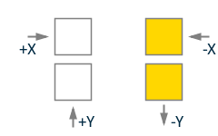
| Direction | Use the Direction box to indicate the direction of the force (X, Y, or both) by clicking on the corresponding box so that the box is marked. One load case will be generated for each direction at which the force acts. | |||||||||||||||||||||||||||||||||||||||||||||
| Mean Roof Height/Structure Height |
Building height used in the calculation of Gust Response and Pressure Coefficients (It is not used in the calculation of the actual exposed area). Building Height refers to the height of the building above ground level as defined in the Ground Level dialog. If parapet height is to be included, it is defined in the Exposure dialog. You have the option to override the program’s selection of Building Height by selecting the third option, Use, and entering a value in the corresponding edit box. See building code for more information. |
|||||||||||||||||||||||||||||||||||||||||||||
| External Pressure Coefficient, Cp | ||||||||||||||||||||||||||||||||||||||||||||||
| Importance Factor |
It is given in table 4.1.7.1 and this parameter is expected to be provided by the user. |
|||||||||||||||||||||||||||||||||||||||||||||
| Exposure Factor, Ce |
Exposure Factor can be determined based on one of the following three options (in calculations below, h is height above ground level, and it is defined in meters):
|
|||||||||||||||||||||||||||||||||||||||||||||
| Gust Effect Factor, Cg |
Gust effect factor can be determined based on one of the following two options (in calculations below, h is mean roof height in meters):
|
|||||||||||||||||||||||||||||||||||||||||||||
| Reference Velocity Pressure, q |
The reference velocity pressure is referenced in Sentence (4) of Section 4.1.7 and this parameter is expected to be provided by the user. Acceptable units are kN/m2 (kPa) psf or kg/m2. |
|||||||||||||||||||||||||||||||||||||||||||||
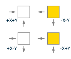
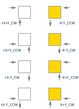
| Loading Directions |
Loading directions Cases A-D as given in Figure I-16 are implemented. Regarding Case B, it is assumed that only half of the building surface is loaded with indicated wind pressures (see the following figure and note that h is the height of the surface.).
Similarly, it is assumed that partial loads are applied to half surface for Case D:
|
|||||||||||||||||||||||||||||||||||||||||||||
| Generate Additional Load Cases for Analysis with Tension-Only Members |
RAM Frame utilizes a nonlinear analysis algorithm to keep track of tension-only members during solution of the structural model under applied loads. Since the process has a nonlinear (iterative) nature, analysis results can not be simply superposed with other results as in load combination option in RAM Frame. Therefore, each lateral load case (wind or seismic) are solved separately. Since the direction of the lateral loads become important in an iterative analysis, RAM Frame provides an option such that additional load cases can be created upon user request. When Generate Additional Load Cases for Analysis with Tension-Only Members in generating lateral load cases (wind and seismic load cases only) is invoked, additional load cases are created. For instance, there are 12 load cases generated for a regular IBC 2000 (ASCE 7-98) Wind load case. If this box is checked, the number of the load cases becomes 22. Additional load cases are created to account for directional effects of applied loads so that the most severe loading case is captured. |