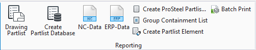
Partlist Creation
 Used to generate a partlist
database (*.mdb) from currently selected steel objects.
Used to generate a partlist
database (*.mdb) from currently selected steel objects.
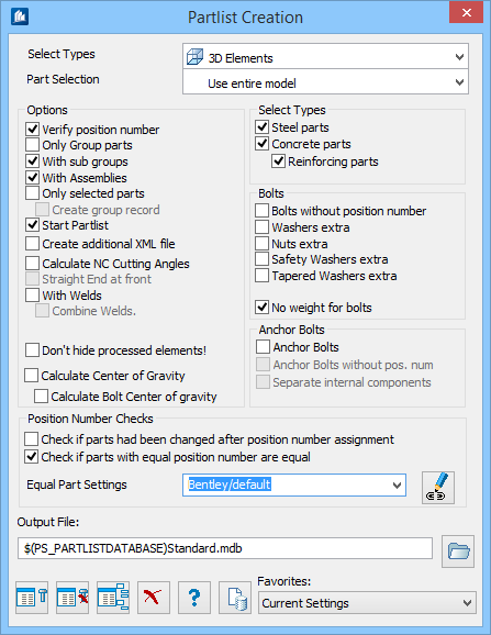
When creating a parts list, you first select the parts to be processed, preferably parts of a group or, in addition, independent single parts.
You can decide whether or not parts of your selection are to be included in the list - either collectively via the filter function during creation of the parts lists or individually for each part. If the ‘Select’ button has not been clicked in the corresponding parts properties, the part will not be included in the parts lists, even though you have selected it.
Since further processing and printing of the parts list is carried out with an extra function, you can register all required parts lists first and store them under different names.
| Setting | Description | |
|---|---|---|
| Select Types | Here, you select the type for parts to be included in the parts list. | |
| Part Selection | Allows selecting the parts on the basis of which a parts list is to be created. | |
| Verify Position Number | Only those selected parts will be taken over into the parts lists that have a valid position number. | |
| Only Group Parts | Only those selected parts will be taken over into the parts lists that are assigned to a group. | |
| With Subgroups | Subgroups are included when the group structure of the parts list is created. | |
| With Assemblies | Assemblies are included when the group structure of the parts list is created. | |
| Only Selected Parts | Only the selected parts are taken over into the parts list. | |
| Start Part List | Parts list processing is started immediately after
creation of the parts list file.
You needn’t use this function separately if you want to continue your work directly. |
|
| Create Additional XML file | In addition to the standard output data (*.mdb), an XML file containing the parts list data will also be created. | |
| Calculate NC, Cutting Angles | The angle of intersection is calculated by ProStructures according to the NC-guidelines of the DSTV. | |
| Straight End at Front | The parts are rotated that the straight end is situated at the front. | |
| With Welds | Information about welds is written into the parts list file. | |
| Don't Hide Processed Elements | Processed elements are not hidden. | |
| Calculate Center of Gravity | Calculates center of gavity of parts in selection. | |
| Steel Parts | Includes Steel parts in the parts list. | |
| Concrete Parts | Includes Concrete parts in the parts list. | |
| Reinforcement Parts | Includes rebar parts in the parts list. | |
| Bolts without position number | Bolts will be included in the parts lists, even if they have no position number. | |
| Washers | Nuts extra | The additional parts for the bolts are separately specified in the list of materials. | |
| Safety Washers extra | Creates additional records for safety nuts. | |
| Tapered Washer extra | Creates additional records for tapered washers. | |
| No Weight for Bolts | Bolts are imported into the parts list without indication of weight. | |
| Anchor Bolts | When checked, uses Anchor bolts. | |
| Anchor Bolts without Pos No. | For Anchor bolts, when checked uses anchor bolts even if they do not have valid position numbers. | |
| Separate Internal Components | Separates internal components in the parts list. | |
| Check if parts had been changed after .. | When checked, the "Check if parts had been changed
after position number assigned" will compare the last position number change
(assignment) time and the last time of part or group change. If the part is
changed after the Position number assignment. the check will detect this and
display information in a text window.
Example: In the case below a
plate has been stretched after the assignment of a position number. If that
position number is used several times, then this element change will not be
reflected in the Partlist and would be the cause of a wrong partlist.
|
|
| Check if parts with equal position number are .. | Enables part equality check. Depending on the
selected criteria to be, it checks if parts with equal position number are
equal.
The drop-down list can be filled with your own criteria. Select a criterion that shall be applied to all parts which shall be used to create that Partlist. If you want to add or change criteria use the Edit Compare Criteria button.
The criterion data are applied to all parts, groups, sub groups or assemblies that are provided with the same position number. Example: A plate has been created and positioned. A copy of that plate was created, and the copied plate was stretched. The length of that plate was changed. There are two plates with same position number but with different length. The criterion selected checks the length of both parts. The report output documents which criteria were checked, which tolerances had been applied and about the compare result. The list is sorted by the position number. It shows the name and ID of both parts. Parts that should be reviewed are marked with a star. In case of two parts both are marked because both are different. You must close that report window (notepad) before
you can continue with your work. Use this report to decide to drop the partlist
output (mdb file) or not.
|
|
| Output File | The file for the list of materials is stored in the file (*.mdb) displayed in the Name field in ‘dBASE-format’. | |
 With Bolts With Bolts
|
Starts part selection with bolts. The selected bolts will be considered as well. | |
 Without Bolts Without Bolts
|
Starts part selection without bolts. Bolts will not be considered, even though they have been selected. | |
 Mounting List Mounting List
|
Starts part selection to create montage parts list. Only the main parts of groups including bolts will be considered. | |
 Cancel Cancel
|
Closes the dialog without saving changes. | |
 Help Help
|
Opens online help. | |
 Template Template
|
Saves and retrieve (Using Templates) settings to be used on other projects. | |
| Favorites |


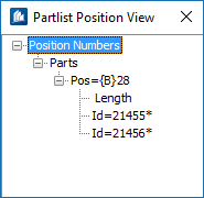
This tree control is filled in addition with group, sub groups and assemblies found in this compare process. If you select a position number or an ID, then the corresponding element is highlighted in the drawing. If you double-click on an ID line, then the property dialog of that element is launched. This element can be a single part or a main part of a group or an assembly object.