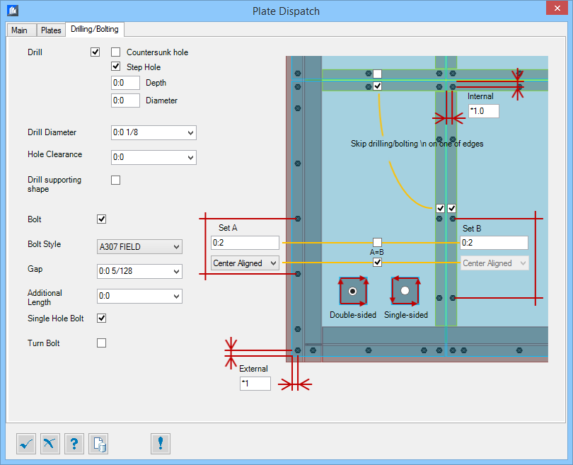
| Drill
|
When checked, drills holes of selected type in the
plate according to the values entered in to alignment fields.
- Countersunk hole
– When checked, the drill type set to countersunk
holes.
- Depth
/ Angle – Sets the depth and angle of the countersunk hole.
- Step
Hole – When checked, the drill type set to step holes. The
corresponding Bolt style can be set.
- Depth
/ Diameter – Sets the depth and diameter of the step hole.
|
| Drill Diameter
|
Sets the diameter of the holes being drilled. Choose a value
from the list, or enter a custom value.
|
| Hole Clearance
|
Sets additional value to the Drill Diameter value, which defines
Clearance for the Holes.
|
| Drill supporting shape
|
When checked, drills holes in the supporting shapes (beams)
aligned with a holes in the Plates.
Note: It is possible to drill supporting shape only if Drill
option (for the plates) is enabled above.
|
| Bolt
|
When checked, adds bolt. It is not necessary to have Drill Holes
using this dialog. Holes may be drilled using different tools, but bolts can be
added using Platform tool.
|
| Bolt Style
|
Sets bolt style selected from the predefined list.
|
| Gap
|
Sets tolerance gap between Beam and Plate to be bolted.
|
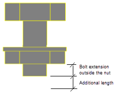
| Additional Length
|
Sets additional length to the bolts extension outside the nut.
|
| Single Hole Bolt
|
Checked, when Supporting shape is not Drilled, in order to
insert bolts.
Unchecked, when Supporting shape is Drilled, and the
Gap value should be more than
0 (Gap>0), in order the Bolts to be
inserted through both elements (e.g. plate and beam).
|
| Turn Bolt
|
When checked, turns bolts upside down.
|
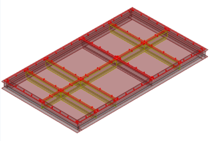
| Set A / Set B
|
Sets the distance between bolts, on a Set A / Set B beams
respectively.
|
| A=B
|
When checked, corresponding values will be unified.
- Distances between
bolts in Set A and in Set B may be unified, and
- Alignment of the
bolts may be unified.
|
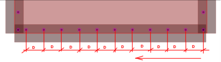
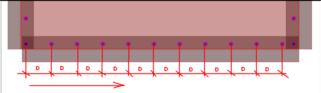
| (Alignment Options)
|
Sets the bolt alignment. Alignment may be different for the Set A
and for the Set B.
-
Center Aligned – From the center of the
beam, towards its ends.
-
Center Half Aligned – From the center
of the beam half aligned.
-
Left Aligned – From the Start point of
the beam.
-
Right Aligned – From the End point of
the beam.
Note: Main four bolts are always placed at the corners of the
Plates, others are defined by distance and alignment.
|
| External / Internal
|
- Sets the bolt position offset from the
outer/external corners/sides of the plate.
- Sets the bolt position offset from the
inner/internal
corners/sides of the plate.
Value entered in multiplier of used hole diameter (e.g. 2
will make center of hole at 40 mm from edge, if hole diameter used is 20 mm)
|
| Skip drilling/bolting on one side
|
When checked, that chosen one edge will be not bolted. This
allows slight movements of the structure without bending the plate.
Note: Only one edge can be not bolted.
|
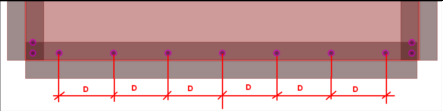
 Double-Sided Double-Sided
|
Alignment layout of the bolts, opposite sides has identical
layouts
|
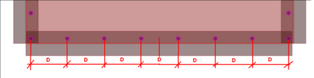
 Single-Sided Single-Sided
|
Counter clock-wise alignment of the bolts starting from the
first beam, added to the particular set (A or B), start point.
|