ProStructures Help

Rectangular Column Reinforcing

Note: Select a link to "jump" to the desired Column Reinforcing tabs.

Column Info

SettingDescription
Section Dimensions - Rectangular columns Used to set the rectangular column section dimensions separately for both Long Face and Short Face. However, the inputs are identical for both.
  • Dimension – (Non editable) Dimension of the column, which is filled in automatically when you select the active column.
  • Bar Quantity – Quantity of bars on the face. If the Opposite Quantity option is not set, the opposite quantity will be set to the same value.
  • Opposite Quantity – When checked, enables setting the values for the Opposite Quantity and Opposite Clearance fields.

    The Opposite Quantity field is the quantity of bars on the opposite face. Only enabled if the Opposite Quantity option is set.

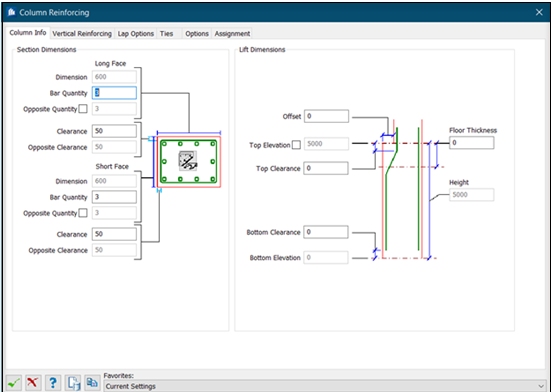
  • Select Active Column – Used to select the active column from the model. If the selected column is circular, then the dialog inputs are updated.
Lift Dimensions
  • Offset – Horizontal distance from the face of the active column to the face of the column above. Can either be typed in or automatically calculated if the user picks the column above.
  • Top Elevation – Top elevation of the active column. Display only and filled in automatically when the active column is selected.
  • Top Clearance – Sets the distance from the top of the column to the top end of the reinforcing cage.
  • Bottom Clearance – Sets the distance from the bottom of the column to the bottom end of the reinforcing cage.
  • Bottom Elevation – Displays the bottom elevation of the active column. Filled in automatically when the active column is selected.
  • Floor Thickness – Sets the thickness of the floor above. Can either be typed in or automatically calculated if the user picks the floor above.
  • Height – Displays the height of the active column. Filled in automatically when the active column is selected.

Vertical Reinforcing

SettingDescription
General group
  • Label – Type a string used to identify the bar. Each label must be unique for the column.
  • Quantity – Total number of bars of the selected type. This field will be display only and will be automatically calculated based on the number of bars specified for all faces on the Column Info tab.
  • Bar Size – Sets the size of the bar selected from the list.
  • Top Offset – Sets The distance from the top end of the rebar cage (determined by the values provided on the Column Info tab) to the top end of the bar.
  • Bottom Offset – Sets The distance from the bottom end of the rebar cage (determined by the values provided on the Column Info tab) to the bottom end of the bar.
  • Remarks – Type a string used for informational purposes only. This value can be included in the label.
Bottom / Top End Conditions The following descriptions apply to both top and bottom options.

Type – Select the type of end condition for each position:

  • Bend – A hook end.
  • Hook – Two 90° bends, creating a hooked parallel leg.
  • Crank – Offset bar
  • 90 Degree Hook – Same as a Bend, but with the angle set at 90°.
  • 135 Degree Hook – Same as a Bend, but with the angle set at 135°.
  • 135 Degree Seismic Hook – Same as a 135 Degree Hook, but with the lengths specified for seismic detailing.
  • 180 Degree Hook – Same as a Bend, but with the angle set at 180°. Or, a hook with a single bend.
  • Projection – Additional straight length.
  • User – User-entered condition with two bends.
Tip: For additional details, Working With End Conditions.
Rotation Type a rotation angle (in degrees). Click to rotate the bar by increments of 90 degrees.
Edit End Condition Values When you select an end condition type, the standard values and angle are applied. If necessary, click Edit End Condition Values to enter custom end condition settings. See Rebar End Properties dialog.
Status Indicates if you have used standard or user-defined end conditions.
(Preview) - the cross section diagram The diagram displays the current number of bars as specified from the Column Info tab. The bar arrangement buttons on the right side of the cross section diagram are used to assign each bar Label to various bar patterns in the cross section.
Rectangular Patterns Vertical Reinforcement Patterns for Rectangular columns. Displays 9 patterns, each when clicked highlights the cross section illustration in the preview.
Adds a new line to the detail table and clears the controls in the editing area allowing a new bar to be entered.

The table displays the details for each vertical bar type added to the reinforcing cage.

Deletes the current line from the corresponding table.

Lap Options

SettingDescription
Basic Data
  • Lap Method – Sets the method for the lap, selected one from the three options: Length, Bar Diameter, and Mechanical Device.
  • Lap Length / Multiplier – When Length is selected as the Lap Method , this value set in the adjacent field will be used for bar laps.

    When Bar Diameter is selected as the Lap Method, then type to use and the calculated lap length is shown in the Multiplier field.

    It is disabled for Mechanical Device method.

Mechanical Device method enables the Manufacturer /Device settings:
  • Manufacturer – Sets All or one of the Manufacturers from the drop-down list.
  • Type – Displays the types of laps. You can set All or one of the Types to narrow the devices list.
  • Device – Lists the devices in a given type for the selected manufacturer. Select required device from the list to proceed lap settings.
Automatic Lap When checked, enables setting automatic lap:
  • Maximum Stock – Sets the percentage to use laps at the maximum bar length. Type a percentage in the % Over field to allow this amount over the maximum length.
  • Stagger Laps – When checked, staggers the bar laps by the indicated distance set in the next field.
  • Stock Length – Sets the bar stock length for the bar size used (default is 60'-0").
  • Min Length – Sets the manufactured length for the bar size used (default is 60'-0").
Manual Lap When checked, enables setting manual lap:
  • Anti-Seismic – When checked, restricts seismic detailing. Enables the Clear Height (Hn) setting.
  • Stagger Laps – When checked, staggers the bar laps by the indicated distance set in the next field.
  • Floor Index / Label – Lists the laps located in the current floor, created with the add tool.
    Note: removes the selected lap from the list.
Current Floor Lap Location
  • Create – When checked, enables setting dimensions and offsets to the lap being added in current floor.
  • Label – Sets the label assigned to each lap added in the list.
  • From Bottom / From Top – Sets the lap location offset measured from either bottom or from top. When
    • Build-In Location – Enabled for From Bottom. When checked, the build-in location is taken for floor lap location.
  • Larger Width (Hc) – Displays the larger width value for the lap.
  • Non Lap Zone – Displays the non lap zones.
  • Bottom Embedded Depth – Sets the depth embedded in the bottom.
  • Clear Height (Hn) – Sets the lap height, for Anti-Seismic lap.
  • Lap Location Offset – Sets the offset distance of lap from the bottom/top.

Ties

SettingDescription
Zone Data
  • Label – Type a string used to identify the tie bar. Each label must be unique for the column.
  • Bar Size – Select the size of the bar from the list.
  • Location – Sets the region of the column for the tie zone: selected one among the options: Start, Middle, or End.
  • Spacing – A value indicating how the ties are to be spaced along the length of the column. Valid entries include lengths and variable or zone spacing formulas.
  • Start / End (Offsets) – Sets distance from the start of the zone to the first tie, and from the end of the zone to the last tie, respectively.
  • Remark –Type a string used for informational purposes only. This value can be included in the label.
  • Via N*Height – For both Start and End offsets, sets the Start and the End spacing for ties using the formula value.
Tie Data
  • Label – Sets the label naming the tie.
  • Offset – Sets the offset to the tie.
  • Remark – Adds a remark string to tie.
Start/ End EC The following descriptions apply to all start and end options.

Type – Select the type of end condition for each position:

  • Bend – A hook end.
  • Hook – Two 90° bends, creating a hooked parallel leg.
  • Crank – Offset bar
  • 90 Degree Hook – Same as a Bend, but with the angle set at 90°.
  • 135 Degree Hook – Same as a Bend, but with the angle set at 135°.
  • 135 Degree Seismic Hook – Same as a 135 Degree Hook, but with the lengths specified for seismic detailing.
  • 180 Degree Hook – Same as a Bend, but with the angle set at 180°. Or, a hook with a single bend.
  • Projection – Additional straight length.
  • User – User-entered condition with two bends.
Tip: For additional details, Working With End Conditions.
Edit End Condition Values When you select an end condition type, the standard values and angle are applied. If necessary, click Edit End Condition Values to enter custom end condition settings. See Rebar End Properties dialog.
Status Indicates if you have used standard or user-defined end conditions.
Adds a new line to the corresponding table and clears the controls in the editing area allowing a new tie zone or bar to be entered.
Deletes the current line from the corresponding table.
Changes the location of the End Condition, can able to change the location of End condition of ties to the next location.
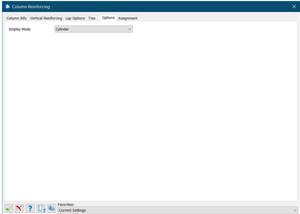
Options

SettingDescription
Display Mode

Sets the mode how rebar displays on your drawing:

  • Line – Rebar and ties display as a single line
  • Cylinder – Rebar and ties display as three dimensional extruded cylinders
Extend to Cover When checked, the length of rebar extends to the edge of concrete minus the cover distance.

Assignments

Assignments are used throughout ProStructures tools to apply special identifiers to drawing objects. Working With Assignments for detailed information.