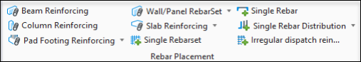
Beam Reinforcing
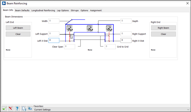
Beam Info


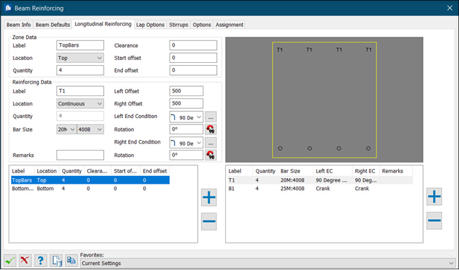
Longitudinal Reinforcing
Used to enter values that define a single reinforcement cage for a concrete beam.
The cross section displays the main reinforcing bars. Clicking a bar in the section when a rebar type is selected in the right table will use this bar type for this bar.
| Setting | Description |
|---|---|
| Zone Data |
|
| Reinforcing Data |
|
| Left / Right Offset | The distance from the left end / right end of the rebar cage to the end of the beam. |
| End Conditions | The following descriptions apply to all start and
end options.
Type – Select the type of end condition for each position:
|
| Rotation | Type a rotation angle (in degrees). Click
 to rotate the bar by increments
of 90 degrees. to rotate the bar by increments
of 90 degrees.
|
 Edit End Condition
Values Edit End Condition
Values
|
When you select an end condition type, the standard
values and angle are applied. If necessary, click
Edit End Condition Values
to enter custom end
condition settings. See
Rebar End Properties dialog.
|
| Status | Indicates if you have used standard or user-defined end conditions. |

|
Adds a new line to the corresponding table and clears the controls in the editing area allowing a new longitudinal reinforcement zone or bar to be entered. |

|
Deletes the current line from the corresponding table. |


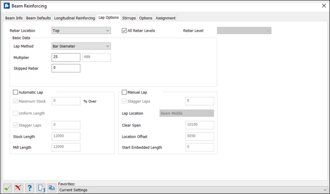
Lap Options
Used to providing settings for beam lap splices.
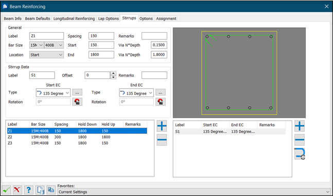
Stirrups
Used to enter values that define a single reinforcement cage for a concrete beam.
As many different types of stirrups as necessary can be entered, with each new stirrup saved as a line in the detail table. The stirrups are defined by clicking the bars in the cross section around which the stirrup is placed. Each Stirrup Zone is used to create a separate spacing or stirrup arrangement along the length of the beam. Each stirrup within a zone is used to specify an individual stirrup at each spacing location along the zone.
| Setting | Description |
|---|---|
| General |
|
| Stirrup Data | |
| Start/ End EC | The following descriptions apply to all start and
end options.
Type – Select the type of end condition for each position:
|
| Rotation | Type a rotation angle (in degrees). Click
to rotate the bar by increments
of 90 degrees.
|
|
Edit End Condition
Values
|
When you select an end condition type, the standard
values and angle are applied. If necessary, click
Edit End Condition Values
to enter custom end
condition settings. See
Rebar End Properties dialog.
|
| Status | Indicates if you have used standard or user-defined end conditions. |
|
|
Adds a new line to the corresponding table and clears the controls in the editing area allowing a new stirrup zone or bar to be entered. |
|
|
Deletes the current line from the corresponding table. |

|
Changes the location of the End Condition, can able to change the location of End condition of ties to the next location. |
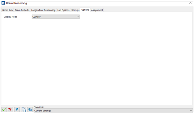
Options
Assignment
As it is the case with each dialog creating component parts, here too it is possible to carry out all assignments directly for each single shape. Select the component part and then select the settings.

Assignments are used throughout ProStructures tools to apply special identifiers to drawing objects. Working With Assignments for detailed information.