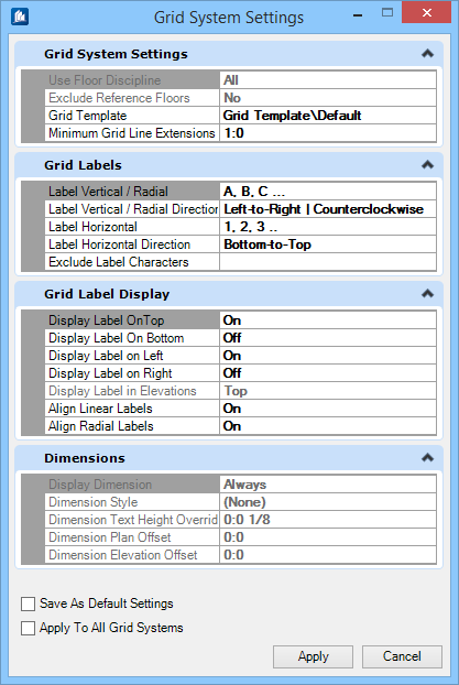
| Grid System Settings
|
Defines default Grid template annotations and set minimum
grid line extension value.
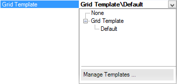
- Grid
Template — Applies the default DGNLib template available at the
location set by the configuration variable
.
Selecting
Manage Templates opens the
Element Templates dialog where the definition of the
Grid Annotation and
Settings used to display the Grid within
a model or used in the production of an external grid model through the
Create/Update Grid Models option.
- Minimum
Grid Line Extension — Sets the shortest distance allowable between
label bubble and the end of the grid line. This is the minimum extension value
defined for the grid lines.
Note: The two
Floor settings are disabled.
|
| Grid Labels
|
Sets label format and their order to suit regional
conventions. This option allows you to define the default labeling format as
either alpha or numeric. (A,B,C… or 1,2,3… ) and the direction of labels.
In practice, Grid labeling requirements differ
region wide to or even project to project. The
Label Direction options allows
you to define the direction in which the grid is defined to accommodate the
appropriate labeling sequence.
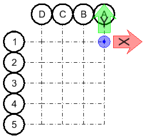
Right to Left / Bottom to
Top
|
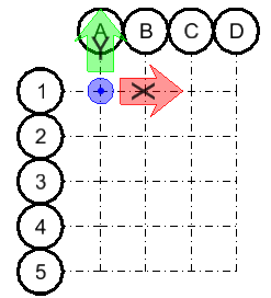
Left to Right / Bottom to Top
(Default)
|
Right to Left / Top to Bottom
|
Left to Right / Top to Bottom
|
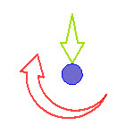
Counter clockwise,
Inwards
|
Counter clockwise,
Outwards
|
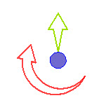
Clockwise, Inwards
|
Clockwise, Outwards
|
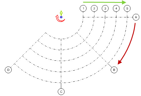
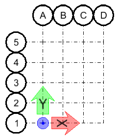
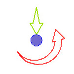
Example of
Counter clockwise, Outwards
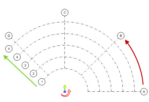
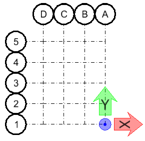
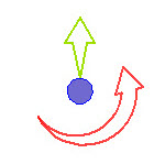
Example of
Clockwise, Outwards
In case of inwards types, the label numbering direction of
circular gridlines starts from outermost grid line and increments towards
innermost.
- Label
Vertical / Radial — Sets the label format either to alpha character
or numeric, auto sequenced in incrementing order. Pick one from the list:
- Label
Vertical / Radial Direction — Sets the vertical or radial direction
of the labels assigned to in grid layout.
- Left
to Right (for Orthogonal) / Counterclockwise (for Radial)
- Right
to Left (for Orthogonal) / Clockwise (for Radial)
- Label
Horizontal — Sets the label format either to alpha character or
numeric, auto sequenced in incrementing order. Pick one from the list:
Applicable to Orthogonal grids.
- Label
Horizontal Direction — Sets the horizontal direction of the labels
assigned to in Orthogonal grid layout.
- Bottom to Top
- Top
to Bottom
Disabled for Radial Grids.
- Exclude
Label Characters — Enter characters (alpha or numeric - as defined
for format), separated by a comma delimiter to skip it from labeling of grids
and in any automated sequencing of the label. This is useful when a certain
character could confuse its impression, e.g. F over E, O over Q etc., practiced
by various CAD standards.
|
| Grid Label Display
|
Sets label display placement and alignment.
- Display
Label on Top / Bottom / Left / Right — Sets to display or not the
label on respective side. Option toggles between:
- Align
Linear Labels — When
On, grid labels are aligned to the
orthogonal grid system regardless of the
Min/max Extents defined. When
Off, grid labels
attach to their parent grid
lines at the selected
Min/max Extents.
- Align
Radial Labels — When
On, grid labels are aligned to the
radial grid system regardless of the
Min/max Extents defined. When
Off, grid labels attach to their parent
grid lines at the selected
Min/max Extents.
|
| Dimensions
|
Note: The
Dimensions settings are
disabled in
ProStructures.
|
| Save As Default Settings
|
Saves as default option, allowing the Grid System
setting to be saved both to the Local and Global storage. Remains pre-set by
default when there is no grid systems defined and the Grid Systems dialog is
empty.
|
| Apply to All Grid Systems
|
Applies the current Grid System Settings to All Grid
Systems, irrespective of selections. This option does not apply setting to the
Global settings, unless Save As Default is also selected.
|