Grid Systems Manager
 Used to set the shape, size,
placement, and appearance of all elements and components contained in a grid
system.
Used to set the shape, size,
placement, and appearance of all elements and components contained in a grid
system.

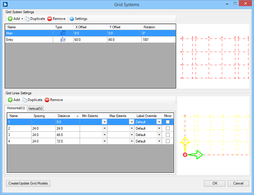
Grid systems functionality offers a column grids utility in which a building can have multiple grids. The Grid Systems dialog contains settings for adding, copying and removing grids, inserting grid lines, manipulating grid line spacing, rotating grids, and setting grid line symbology and other preferences.
In addition to creating grids, the Grid Systems functionality can import grid system information originating in external applications such as RAM Structural System, and reconstitute them inside ProStructures. Both the ISM import tools (New from ISM Repository and Update from ISM Repository) can be used for this. Also, new grid systems and changes to existing (imported or natively) grid systems can be exported via ISM export tools (Create ISM Repository and Update ISM Repository).
Grid System Settings toolbar
| Setting | Description |
|---|---|
| Add | Used to add new grids to the grid system. The new grids can then be manipulated using the available Grid System Settings. The new grid is added at the end of the grid systems list. Similar Grids added in succession will have incremental number prefix added to its definition, e.g. RadialGrid, followed by RadialGrid1 etc. |
| Duplicate | Used to copy existing grids. The copies appear in the row below the selected grid definition. |
| Remove | Used to delete existing grids from the grid system list. Selected grid definitions are removed using the Remove or by pressing <Delete>. |
| Settings | Opens the Grid System Settings dialog where default settings for how Grid Systems are presented, labeled and dimensioned are managed. |


Grid System Settings table
Used to manipulate grids. Selecting a grid row activates the settings for that grid.
Grid Lines Settings toolbar
| Setting | Description |
|---|---|
| Add | Used to add new grid lines to selected grid definition. New grid lines appear at the end of the grid lines table with next incremental Label in Name. |
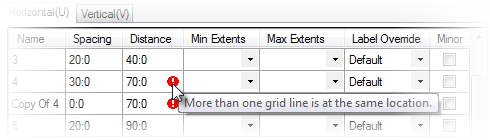
| Duplicate | Used to copy existing grid lines. The copies appear in the row below selected grid line in the table. Disabled for Sketch grid definitions. Duplicated grid lines inherit properties of the selected grid line. The alert message indicates the grid line at the same location, until you amend the Spacing and/or Distance value. |
| Remove | Used to delete existing grid lines from the grid lines table. Selected grid lines are removed using the Remove or by pressing <Delete>. |
Grid Lines Settings table
Used to manipulate grid lines. Selecting a grid line row activates the settings for that grid line.
| Setting | Description |
|---|---|
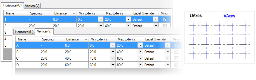
| Horizontal (U) | Vertical (V) tabs | Enabled when orthographic grids are selected from the Grid Line Settings table. |
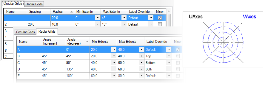
| Circular Grids | Radial Grids tabs | Enabled when radial grids are selected from the Grid Line Settings table. |
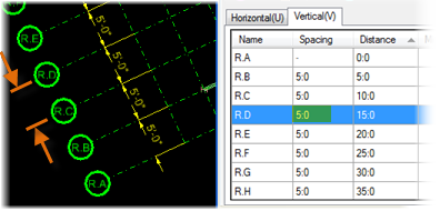
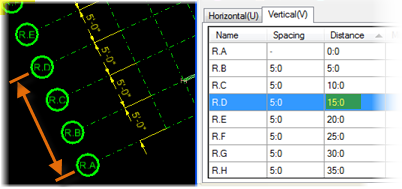
| Name | Used to enter the grid line label for the selected grid line. Follows the default Grid Labels scheme set in the Grid System Settings dialog. |
| Spacing | Enabled on the Horizontal(U), Vertical(V) and Circular Grids tabs. Displays and sets the distance or angle between the selected grid line and the preceding grid line on the grid lines table. Accumulated distances or angles (measured from the grid origin) are calculated and displayed in the adjacent Distance column. |
| Distance | Enabled on the Horizontal(U)/Vertical(V) tabs. Displays and sets the distance between the selected grid line and the grid origin. Values entered here override the Spacing value for the selected grid line only. |
| Radius | Enabled on the Circular Grids tab only. |
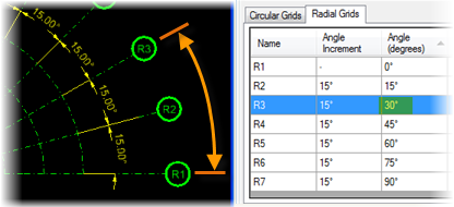
| Angle Increment | Enabled on the Radial Grids tab only. Sets the angle incremental value from previous grid line. |
| Angle (degrees) | Enabled on the Radial Grids tab only. Displays and sets the angle between the selected grid line and the grid origin axis. Values entered here override the Spacing value for the selected grid line only. Positive values rotate grid lines counter clockwise. |
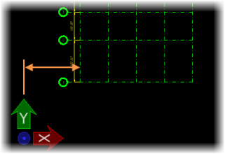
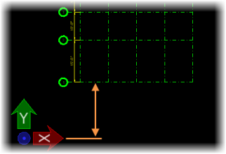
| Min Extents | Select the intersecting grid line to determine the smallest extent for the grid line being changed. The value is set by selecting an option from the options available in the drop-down. |
| Max Extents | Select the intersecting grid line to determine the
maximum permissible extent for the grid line being changed. The value is set by
selecting an option from the options available in the drop-down.
The options under Min Extents are always smaller than the options in Max Extents. When set the option put in the step value of the uniformly spaced grids. In both Extents settings the line and the label are moved. |
| Label Override | Used to override the label position set in the Grid
System Settings dialog. Select from one of the available options on the
drop-down list.
|
| Minor | Indicates the type of grid line the selected grid
line is. Check to set it to
Minor. Unchecked grid lines indicate default
Major.
The primary grid line in a grid usually uniformly spaced relative to other grid lines. A secondary grid line within a grid used for locating columns which are exceptions to an otherwise uniform, regular grid layout or pattern are set as Minor. |
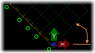
Previews, Create Grids/Models
Used to preview the grid systems graphics. Displays the grids defined for the selected floor. Grid lines, grid bubbles and labels are displayed. Selected grids are displayed in red. Deselected grids are displayed in green.