General Information - Detail Types
At detailing, the DetailCenter differentiates between different detail types, such as single parts or component part groups. In most cases, these definitions come from 3D-modelling so that you don’t have to take into account anything else.
Single Parts
These are all parts that correspond to a real 3D-component part in the model and normally are the smallest unit of detailing. The DetailCenter itself, however, cannot differentiate between production parts and parts of additional purchase or on stock.
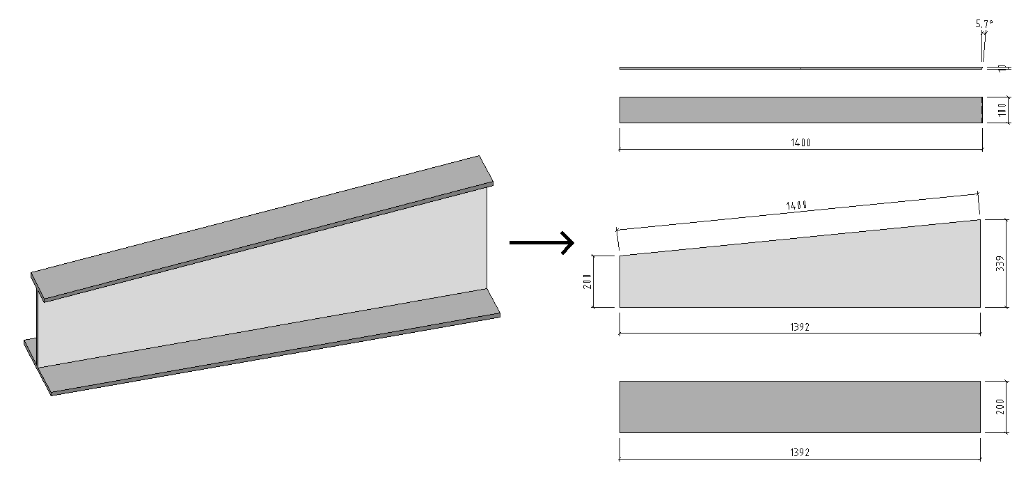
A single part drawing can be generated of every ProStructures volume solid. In this drawing, the part edges, angles of intersection and drill holes are dimensioned. Normally the coordinate system of the component part defines the alignment of standard views, such as front view, plan view, etc.
Component Part Groups
This is a logical arrangement of single parts that you have already created in the 3D-model by using the command ‘Groups’.
A drawing of the component part group is created so that the add-on dimensions of the single parts and/or groups to each other are dimensioned. It is also possible to insert subordinate structures and single part dimensions of component parts.
Views
This is a three-dimensional arrangement of component parts in the model as they can be seen from a defined view direction and with a previously defined view depth, which is not to be confused with the component part views.
An overview drawing is created in which the position of the component parts to each other and to existing reference axes (constructional axes) is dimensioned.
Views are derived from the existing model views which were either created automatically by the workframe, or which were added by you later.
Isometric Views
These views show the model in a three-dimensional depiction and are often desired without the hidden edges. View direction is determined by the five global 3D-model views of the configuration.
It is possible as well to add isometric views to individual details (e.g. groups). In this case, these are depicted as component part view together with the other partial views.
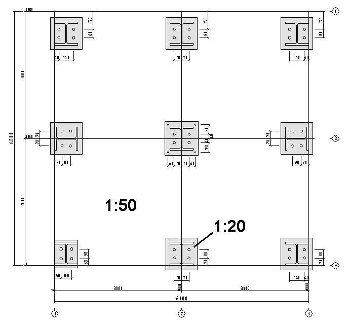
Anchorage Plan
This view refers to the plan view plane and shows the plan view including dimensions together with the depiction of the base plates and supports.
As special feature, it is possible to use different scales for plan view and base plate details. The dimensioning of the holes can be referred to the plan view grid.
Manual Details
In principle, these are also views of the model, but you can freely determine the involved component parts and the view direction during detailing.
Manual details allow you to generate unusual views or special detail sections. As the name implies, you have to attach the dimensioning yourself and you don’t have any possibility to have the view automatically checked with regard to modifications.
Manual details don’t appear in the component part list nor do they have their own detailing style. Scale and display of the component parts are, however controlled by a temporarily assigned detailing style during generation.
It is true that after generation manual details can be inserted into the drawing in the same way like standard views.
Multi-Shapes
These are single parts consisting of several components that are normally treated and dimensioned like a single coherent component part (e.g. weld shapes).
Depending on the situation it may be that these component parts are not ordered but individually produced. Therefore, in the DetailCenter you can consider a multi-shape as components. That means that it appears as an individual subpart in a component part group, but on the other hand you can still create single part drawings of the components.
Gusset Details
These are views on the model showing the involved component parts of a connection (2) or of a group of connections (1) as detailed section.
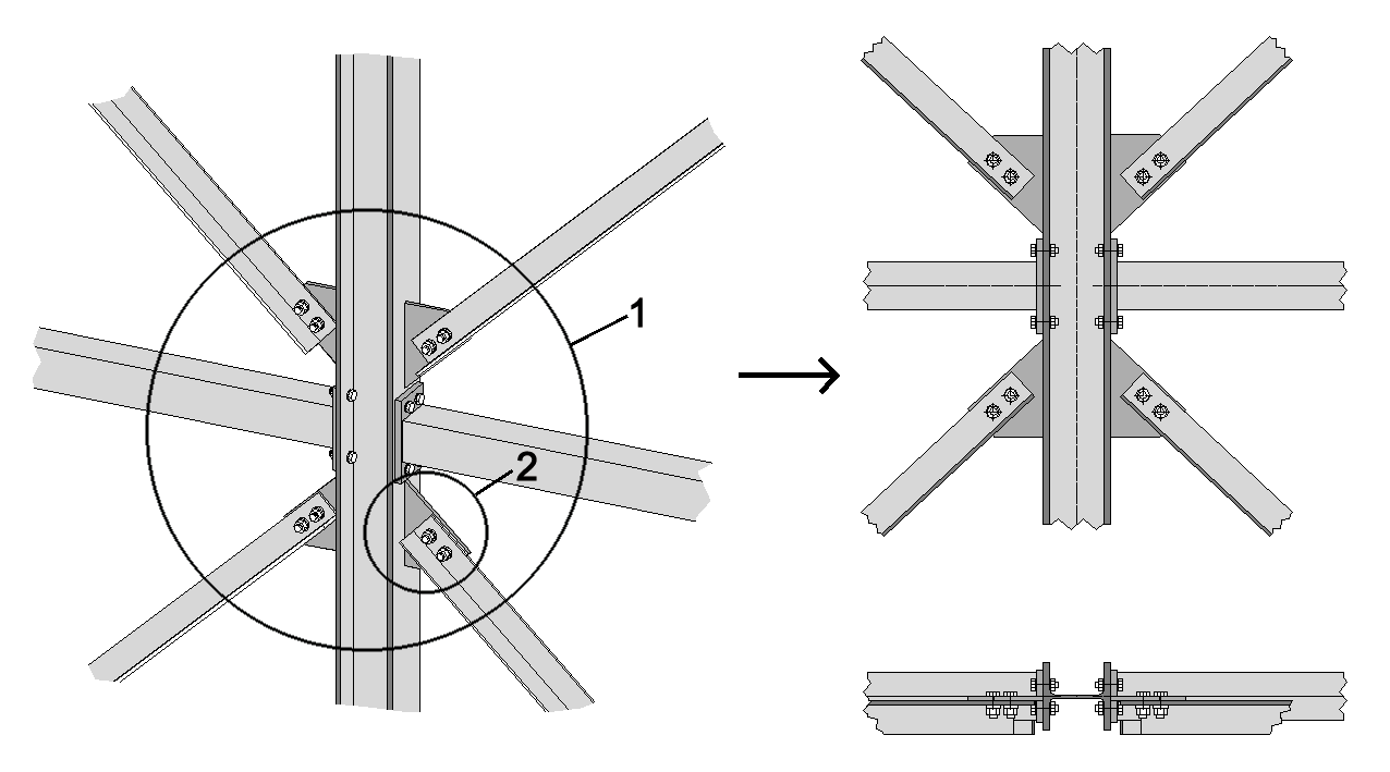
In most cases, the connecting elements such as plates, bolts, etc. can be completely seen whereas the connected shapes are only partially displayed. The connections are recognized via the existing logical links if at least one of these links is named with an identification code.
A gusset detail appears as separate ‘component part’ in the component part list of the DetailCenter and a detailing style can be assigned to it. Afterwards, you treat it in a similar way like a component part group.
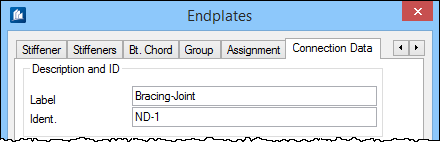
Create Named Connections
For this purpose, activate the ‘Extended Inputs’ for logical links in the global settings of ProStructures, if not yet effected. In the property dialog of the connection, you can now enter a clear identification code and optionally a designation.
Assignment to Common Gussets
If there are several connections in one three-dimensionally coherent area, a common gusset detail can be created out of these connections. Only one of the involved connections has to (and should) have an identification code.
The main shape of this connection now defines the alignment of the gusset detail. Within a search area (defined by you in the global settings of the DetailCenter) all other connections are now assigned to this gusset. Then, they won’t create an own main entry any more – even if they themselves have a code.