ProStructures Help

Adding straight shapes

To add straight shapes to your model, use the following procedure.
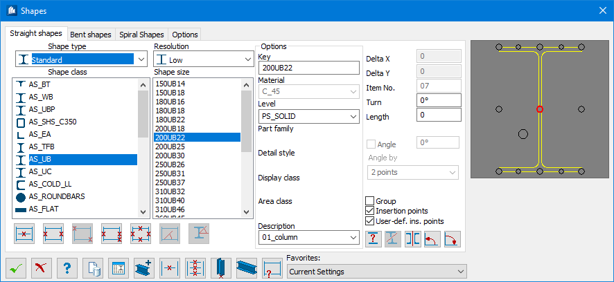
  1. Either:

    Select the Shapes tool.

    or

    Key in ProSteel Place Shape .

    The Shapes dialog opens.
  2. Select Shape type.
  3. Select Shape class and then Shape size.
  4. (Optional) Complete the Options group of the Shapes tab to set the Assignments for the shape.
  5. Select the insertion point by clicking the appropriate circle in the cross-section diagram (select point will turn red).
    Note: As you click on an insertion point, the Delta X and Delta Y dimensions updates.

    If you select the user-defined insertion point (the larger circle off-center, then you can manually enter values for Delta X and Delta Y.

    Tip: The handles are also placed on either end of the shape, in line with the selected insertion point.
  6. Either:

    Type a dimension for Length if you will place by a point (second point will only be used for direction if a Length is entered).

    or

    Set Length to zero if you will place by line or by two points.

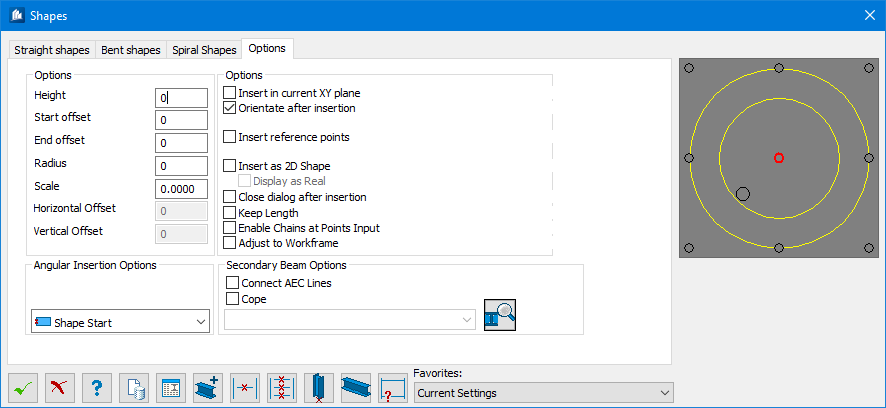
  7. For additional options (Height, Start Offset, End Offsets & etc..), select the Options tab.
    1. Height
    2. Start Offset
    3. End Offset
  8. Place your beams or columns around the work frame using one of the following methods on the Shapes tab:
    Option Description


    Insert Concrete Shape by a Line
    Click on a line to place the beam along the line. Length is determined by the line; you do not need to enter a length dimension.

    Right-clicking will rotate the beam by the default value (90º) or click to accept. You can pick another link or click to return to the Beam dialog.


    Insert Shape by 2 Points
    Click beginning and ending points to place the beam to the length you choose. Length is determined by the points you select; you do not need to enter a length dimension. This method is commonly used to place beams and columns by clicking on grid line intersections.

    Right-clicking will rotate the beam by the default value (90º) or click to accept. You can pick another link or click to return to the Beam dialog.

    Insert Shape Diagonally by Two Points


    Insert Shape by 3 Points
    Click beginning and ending points to place the beam to the length you choose. Length is determined by the points you select; you do not need to enter a length dimension.  The third point determines the shape rotation.

    Right-clicking will rotate the beam by the default value (90º) or click to accept. You can pick another link or click to return to the Beam dialog.


    Insert Shape on Multiple Lines
    Click on a line to place the beam along the line. Length is determined by the line; you do not need to enter a length dimension.

    You can pick another link or click to return to the Beam dialog.

    Note: You will not have the option to rotate the beam after selecting the lines using this method.


    Insert Beam Between 2 Main Beams
    Select two beams. Set your beam spacing from start point of beam. Beams place at insertion point based on spacing entered.


    Insert Multiple Beams Between 2 Beams
    Select two beams. Set your Offsets from Start Points.  The command will draw a beam between the selected beams.
    Insert Column at selected points Click on this button to insert the column at the position to be picked and to divide it into segments corresponding to the list.


    Insert Beam at WorkFrame Axes
    Click to place a rectangular selection along the current XY axis, any workframe axes inside of the area selected will get a beam from grid line to grid line.
    Tip: At any point when you are placing elements, you can right-click to reopen the dialog and make changes.
  9. Click OK to apply your settings and close the dialog.