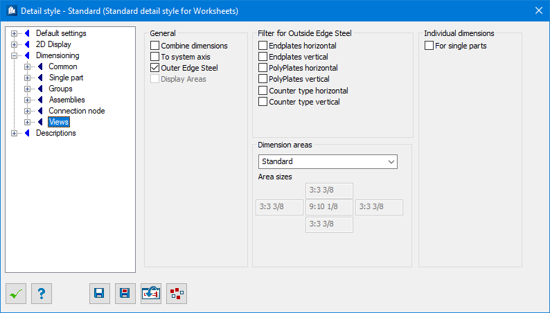
| General
|
Dimensioning criteria settings:
|
| Connect Dimensions
|
Similar inner dimension chains which are situated
close together are connected to one common dimension chain each.
|
| To System Axis
|
Only the axis distances of the outer profiles are
used to calculate the total dimensions of the entire steel construction (outer
edge steel).
|
| Outer Edge Steel
|
The definition of the outer edge steel of the
construction (including filter) is used as the total dimensions of the view and
as the reference point ‘View’. Otherwise the outer grid axes are used for this
purpose, if represented..
|
| Display Areas
|
The determined dimension areas (if local areas have
been activated) are displayed in color for control purposes.
This option is only an auxiliary for the
configuration of the local areas and should normally be deactivated.
|
| Filter For Outside Edge Steel
|
Here, you have the possibility to exclude certain
parts from the calculation of outer dimensions to prevent it from increasing
e.g. by the projection of base plates.
|
| Endplates horizontal
|
End and base plates in horizontal direction (width)
are not taken into consideration.
|
| Endplates vertical
|
End and base plates in vertical direction (height)
are not taken into consideration.
|
| Poly-plates horizontal
|
Poly-plates and stiffeners in horizontal direction
are not taken into consideration.
|
| Poly-plates vertical
|
Poly-plates and stiffeners in vertical direction are
not taken into consideration.
|
| Counter Type horizontal
|
The shape type opposite to the view (i.e. at views
the shapes in cross-section display and at plan view the shapes in view
display) in horizontal direction is not taken into consideration.
|
| Counter Type vertical
|
The shape type opposite to the view (i.e. at views
the shapes in cross-section display and at plan view the shapes in view
display) in vertical direction is not taken into consideration.
|
| Dimensioning Area
|
Here, you determine the principle method for
component part dimensioning in views.
- Standard – All
shapes are dimensioned outside the view.
- Only Outer Area
– Shapes which are situated in the defined outside area are dimensioned outside
the view. All other shapes are not dimensioned.
- Outside and Inside
areas – Shapes which are situated in the defined outside area are
dimensioned outside the view. Shapes which are situated in the remaining inside
area of the view are locally dimensioned.
- Outside and Area
Analysis – Local inside areas of the view are automatically
determined according to your defaults. Shapes which are situated in the defined
outside area are dimensioned outside the view. Shapes which are situated in the
determined inside areas are locally dimensioned.
- Outside Areas and
Assemblies
– Shapes and assemblies which are situated in the
defined outside area are dimensioned outside the view.
You can give additional information on a separate
page of this parameter group.
For more detailed information about inside and
outside areas of a view, please refer to the general explanations of
—Local Areas in Overviews under "Dimensioning Areas".
|
| Area Sizes
|
Here, you indicate the distance from the
corresponding outer edge of the view to the inside up to which a shape is still
assigned to the outer area.
- Inner
Field – Here, you enter the size of the sections into which a local
inner area is additionally subdivided. Each section can contain its own local
dimension chains.
The size is an approximate value and can be bigger or
smaller in reality. If you enter the value 0, the areas are not subdivided any
more.
For more detailed information about inner and outer areas of
a view, please refer to the general explanations concerning local areas in
overviews.
- Outer
Fields – Here you enter the distances of left, right, lower and
upper side individually.
|
| Individual Dimensions
|
Dimensions all parts individually like single parts, when the
for single parts option is checked.
|