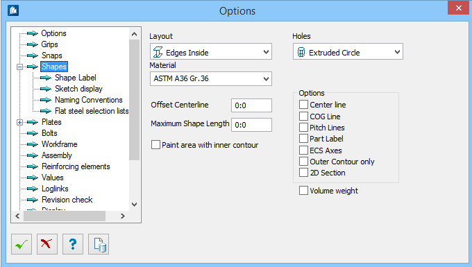
| Layout
|
Sets the mode in which new elements will be
displayed when inserted in the model.
Options available are:
- Only Centerline
- Bounding Box
- Edges Outside
- Edges Inside
- With Arcs
- As Sketch
|
| Holes
|
Sets the mode in which holes are displayed in new
elements.
Options available are:
- Do not Display
- As Line
- As two Circles
- Extruded Circle
- Real Holes
|
| Material
|
Sets the selected material to be used for the shape
|
| Offset Centerline
|
You specify the length beyond which the centerline
has to exceed the shape ends.
|
| Maximum Shape Length
|
Sets the maximum global length extend. If you type a
value bigger than 0 and you have checked the option
Verify Shape Lengths on the Options tab, and
shapes are inserted, a message is displayed drawing your attention to the fact
that the maximum delivery length is exceeded by some shapes.
A hint dialog appears and the corresponding shapes
are highlighted in color.
|
| Paint area with inner contour
|
When checked, includes the inner face area of hollow
shape into paint area calculation.
|
| Options
|
Sets the options to display new inserted shapes
with:
- Centerline –
with centerline.
- COG Line – with
COG lines.
- Pitch
Lines – with pitch lines
- Part
Label – with Name.
- ECS Axes – with
ECS.
- Outer
Contour Only – plates with outer counter only.
- 2D Section –
with 2D cuts.
|
| Volume Weight
|
When checked, computes the weight of the parts from
the used volume.
|