Boundaries
Boundaries are pipe ends that do not end at equipment nozzles or other pipelines. Typical boundaries are off page connectors (OPC) and end of pipeway (EOP) for utility headers. To define a boundary component, select from the PlantWise window. This opens the Boundary List dialog
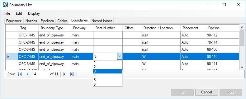
To define a new boundary:
- Enter the Boundary name in the Tag column.
- Enter or select with the
selection box the
Boundary Type. The allowable entries are given
as
<element type> in "Boundary Input
(.rpb file)".
There are several kinds of boundary components. They are identified as follows:
- EOP = End Of Pipeway boundaries are for pipelines that terminate at the end of a pipeway as a capped end or battery limit.
- EAB = End At Bent boundaries allow you to end a pipe at a specified bent in the pipeway. You can also indicate an offset from the indicated bent.
- Outlet boundaries act as an endpoint for a pipeline without being associated with a pipeway. Unless placed beforehand, outlets will automatically place during routing and can be moved afterwards. Pipelines with two unplaced outlet ends will not be routed automatically – at least one end must be manually placed first.
- Floating_end is a boundary component that is automatically defined by the program when you cut a pipeline with a Fenced Submodel.
- If the boundary is an
end-of-pipeway (EOP) or an end-at-bent (EAB), select the pipeway on which this
boundary lies using the Pipeway column.
-
Select the end of the pipeway where the boundary is using the Location selection box. The selections are N, S, E, W as well as Start, End, Top, and Bottom (Top and Bottom are for boundaries associated with vertical pipeways).
If the boundary is an end-at-bent, enter the bent number and the offset from that bent.
-
- If the boundary is an Outlet, select the location. Location for an outlet boundary sets the direction the pipeline end should be directed towards.
- Apply creates the boundary object in the process model and adds the boundary into the boundary list.

Boundary List Menus
Like the Pipeline List, the Boundary List dialog contains two menus: File and Edit.
The File menu allows you to save the model (Save Model), save the model under another name (Save Model As), and exit the dialog (Close).
As well as deleting a boundary, the Edit Menu allows you to: rename a boundary (Rename Boundary), enter the Pipeline Editor (Pipeline), enter the Connectivity Editor (Connectivity), and enter the Pipeway Editor (Pipeway).
To exit the Plant Builder Boundary List dialog, click the Cancel button. Information not Applied is discarded.