Vertical Chases
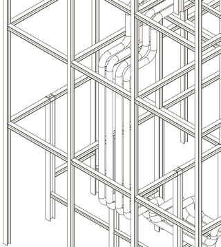
Building a vertical chase
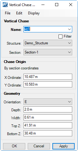
Vertical Chase Builder
The Vertical Chase Builder, shown below, has three menus:
| Setting | Description |
|---|---|
| File menu | |
| Edit menu | Delete Vertical Chase. |
| Display menu |
|
The Vertical Chase Builder, shown below, has three menus:
| Setting | Description |
|---|---|
| File menu | |
| Edit menu | Delete Vertical Chase. |
| Display menu |
|