| Group menu
|
|
| Component menu
|
This menu can also be accessed with a right mouse
click while the mouse pointer in the component list)
- Edit opens the
Editor or Builder for the selected component.
- Remove
from list removes the component from the group.
- Zoom
To causes CAD to prompt for a view to be zoomed.
- Highlight draws
the component on the Highlight layer in CAD.
- UnHighlight
draws the component on its default or user-set layer.
- UnHighlight All
draws all highlighted components on their default or user-set CAD layers.
|
| Help menu
|
Display help opens Help in
the workstation’s default web browser.
|
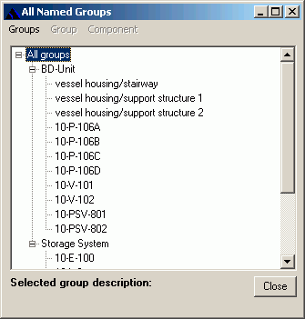
| Component List and Action Selection
|
The component list is the name and component type of
all the members of the groups. As discussed above, you can remove items from
the list, but items cannot be added.
The
Action selection is how you select a group
functionality, and then enter the action’s value.
|
| Move
|
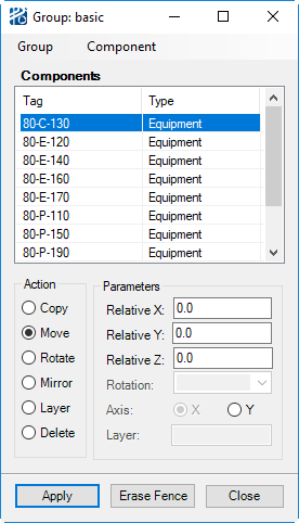
The Move action translates the group by the values
entered into the X, Y, and Z fields.
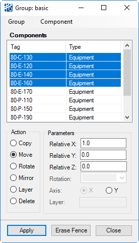
Group
Movement Dialog - Move Option
Note: if a placeable
inline component - such as a control valve - is included in a group, the
placement of the inline after a group move will be determined by the router. If
the inline has been frozen, then its placement after a group move will be a
relative offset from its previously frozen position.
Groups can also be moved dynamically through CAD.
After selecting the group, you can then click on the
Dynamic Copy/Move button from the
Plant Toolbox. You then select a base
point followed by a destination point.
Note: The Move
action radio button must be selected in the Group Movement dialog for the
dynamic move to work.
|
| Rotate
|
The Rotate action rotates the group 90, 180, or 270
degrees about the group’s center. The center of the group is approximated by
calculating the center of the box that is created by the outer-most placement
points of the items in the
Objects to Move list. Because placement
points are different for different types of equipment, the rotation point for
the
Group Rotate will generally not be the exact
center of the group.
For equipment and structures, you can enter any
rotation angle in the
Equipment/Structure Angle field. If there
are other types of components in the list, you will be prompted with errors
stating that,
Only equipment and structures can be rotated by non orthogonal rotations.
Note: Only
structures without structure pipeways, vertical chases, or vertical pipeways
can be rotated arbitrarily.
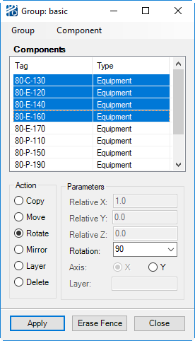
Group
Movement Dialog - Rotate Options
|
| Mirror
|
The Mirror action mirrors a group about a local axis
parallel to the global X or Y axis passing through the group center as defined
in Group Rotate.

Group
Movement Dialog - Mirror Options
Note: Structures,
pipeways, and other steel members cannot be mirrored.
Note: Only placement
points are mirrored, not geometry.
|
| Copy
|
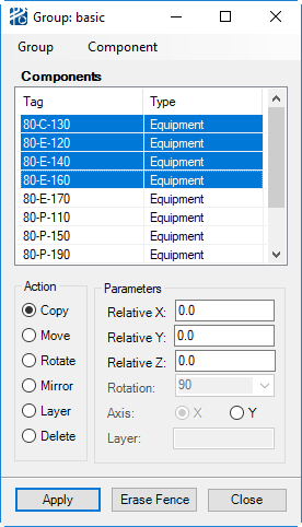
The Copy action copies equipment and obstacles and
place the new objects by the offset entered in the Relative Movement area.
Note: Pipelines,
structures, pipeways, and frozen inline components cannot be copied.
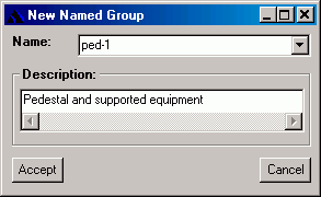
The new items are named incrementally for items
with delimiters in their name. Some standard delimiters are periods
( .) and hyphens ( -).
PlantWise adds to the number or
letter (less than z) that follows the delimiter. If the item does not have a
delimiter in its name,
PlantWise adds a hyphen followed by
one (-1) for the first copy and then continue the count from there. Examples of
incremental naming are shown in the table below.
| Original
|
Copy
|
| Tank-1
|
Tank-2
|
| Tank.003
|
Tank.004
|
| 0123-a
|
0123-b
|
| 02-987x
|
02-987y
|
| 03-456-Z
|
03-456-Z-1
|
| 80-T-100
|
80-T-101
|
| 80-T-100-PLATF
|
80-T-100-PLATF-1
|
| 12345M
|
12345N
|
| Crane1
|
Crane2
|
| EXCH-STR-PLAT1B
|
EXCH-STR-PLAT1B-1
|
Groups can also be copied dynamically through CAD. After
selecting the group, and then selecting the Copy action, you then click on the
Dynamic Copy/Move button from the
Plant Toolbox. You then select a base point
followed by a destination point.
|
| Delete
|
Deletes the equipment and obstacle items in the list
from the model.
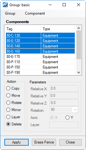
Group
Movement dialog - Delete Options
|
| Set Layer
|
Draws the group’s equipment and obstacle components
to the specified CAD drawing layer.

Group
Movement dialog - Set Layer Options
|
| Command Buttons
|
With the command buttons, you:
- Accept the
actions to be taken
- Erase the fence used
to create the group (Erase Fence)
- Close the
dialog
|