Structural Members
Independent structural members (ISMs) give users the ability to add individual members to their models. These members can be used to add extra bracing for pipeways or structures, better model individual pipe supports, and so on. Members can be associated with a structure or pipeway; if so associated, the member will maintain its relative placement with respect to the structure if the structure is moved or rotated. As with other structural members, ISMs are seen as obstacles to the AutoRouter and are included in steel reports.
To add an ISM, you can either open an empty Structural Member Builder ( from the PlantWise dialog or PlantWise menu in CAD); place a smart line in the desired location of the ISM and then click the Place Member tool icon on the Structure Toolbox; or, fill in the new member properties and location in an already filled in Structural Member Builder and click the Create button.
Structure Member Builder
You can edit individual structural members (independent or those associated with a structure section) via the Structure Member Builder. The Structure Member Builder is opened for a specific member by selecting the member after clicking the Edit Member tool icon on the Structure Toolbox or by double clicking on the member designation in the Structure Bay Editor.
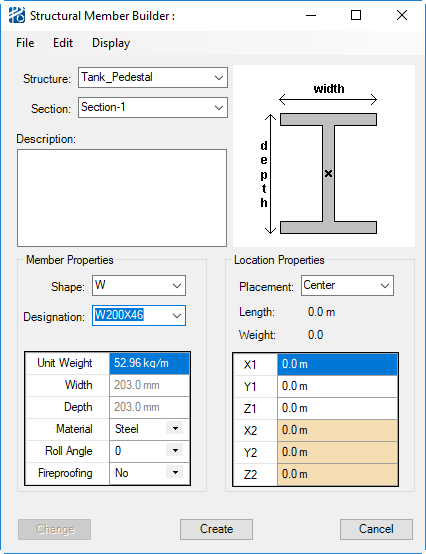
If a new member is to be associated with a structure or pipeway section, then that section is selected from the Structure and Section drop down lists. All existing structures and pipeways will be listed in the Structure drop down and the existing sections for the selected structure/pipeway will then be listed in the Section drop down.
You can also add notes to the member in the Description text field.
To the right of the Description box is a graphic of the shape currently selected. The small X on the graphic indicates the location the placement axis runs through the member section. For most shapes, the default location is in the center of the member. You can, however, change the placement of the member in the Placement drop down list in the Location Properties pane of the dialog (see "Location Properties" below).
| Setting | Description |
|---|---|
| Member Properties | All available member shapes and designations are
listed in the structural-member-properties table. Although
you can add any designation, only the following shapes are available:
Once you have selected a Shape and Designation, the data table will fill in the following fields: With the exception of Material, you cannot edit data table values in the Structural Member Builder. Un-editable attribute values are written in dark gray rather than black. You need to add new designations to the structural-member-properties table to customize member dimensions. There are two additional Member Properties attributes: |
| Location Properties | In the Location Properties section of the
Structural Member Builder, you define placement method
and endpoint coordinates.
The Placement drop down list allows you to select whether the member is to be placed by Top, Center, or Bottom of steel. When a new placement is selected, the X indicating the placement location in the member graphic will update. Note: The Structural
Member Builder always opens with the placement set to Center – or Top for
members that are only placed by top of steel.
Note: When the
changed Placement is accepted, the dialog will update the endpoint coordinates
to the updated center of pipe location and the Placement will be reset to
Center.
Below the Placement drop down list, the total Length and Weight of the member are listed strictly for reference. Placement of the member is based on the endpoint ordinates provided in the X1, Y1, Z1, X2, Y2, and Z2 fields. |
| Command Buttons | The
Change button will apply changed attribute
values to an existing member.
The Create button will generate a new structural member. It should be noted that the Create button is only enabled under specific circumstances:
The Close button will close the dialog without saving any changes since the last Accept or Edit. |
| Menus | From the
File menu you can
Save Model,
Save Model As, and
Close the dialog.
From the Edit menu, you can:
The Display menu gives you the ability to Zoom To, Highlight, and UnHighlight members; redraw the structure section if your suspect that PlantWise and the CAD are not consistent (Redraw); or open the Mass Properties dialog for the current member (Mass Properties). |