Vertical Pipeways
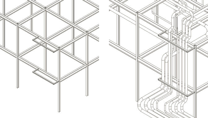
Vertical pipeways
represent a vertical routing space with support members attached to the outside
of a structure.
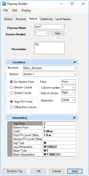
The Vertical Pipeway Builder, shown below, has three menus:
| Setting | Description |
|---|---|
| File menu | |
| Edit menu: | |
| Display menu |
|
Building a vertical pipeway
- Open the Vertical Pipeway Builder from the PlantWise window ().
- Enter the identification information in the Vertical Pipeway section of the dialog,
-
Enter the location information in the Placement section of the
dialog,
- choose a placement Method
-
Enter the placement of the pipeway.
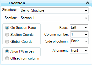
- If the placement
method of the pipeway is
On Section face, the locational
section is labeled
Face. In this area you pick the face
of the structure on which the pipeway is placed, a
Column Number on that face (starting
from 1), the
Side of column on which the pipeway
is to be placed, and the alignment of the pipeway within the bay. The two
alignment options are to provide an alignment for the pipeway in the bay or to
select a value to offset the pipeway from the column.
- If Align PW in bay is selected, you will pick from three positional options in the Alignment in bay drop down list (center or the two directions perpendicular to the face direction).
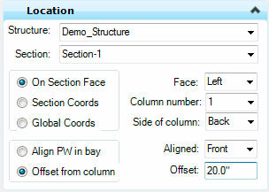
- If Offset PW from column is selected, you will enter an Offset from column value and the relationship of the pipeway to that value in the Place pipeway drop down list (center or the two directions perpendicular to the face direction).
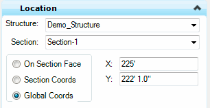
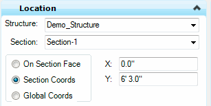
- If placement
method of the pipeway is
By coordinates, the locational
section is labeled
Centerline location by. From
here you select either global or section coordinates.
Section coordinates use the placement point of the structure section as the origin.
- If the placement
method of the pipeway is
On Section face, the locational
section is labeled
Face. In this area you pick the face
of the structure on which the pipeway is placed, a
Column Number on that face (starting
from 1), the
Side of column on which the pipeway
is to be placed, and the alignment of the pipeway within the bay. The two
alignment options are to provide an alignment for the pipeway in the bay or to
select a value to offset the pipeway from the column.
-
Enter the physical data in the
Geometry section of the dialog.
- The Bottom Floor Level is the lowest rung of the pipeway section.
- The Top Floor Level is the highest rung of the pipeway section.
- The Leg Shape and Beam Shape are the steel members of the pipeway and are selected from the steel table.
- The First PW Level Offset is the depth of the inside level of the pipeway.
- The Second PW Level Offset is the depth of the outside level of the pipeway.
- Width is the distance between column center lines in a bent.