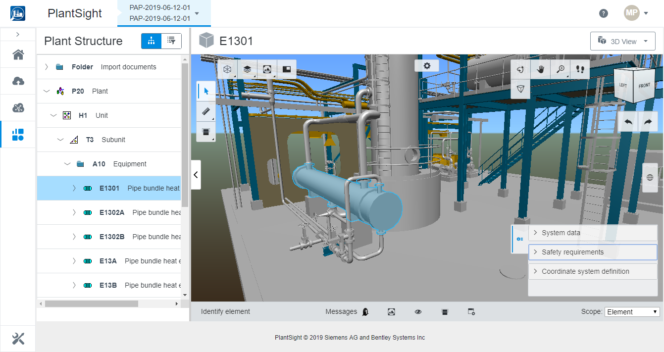
Models Models
|
Used to filter the model based on predefined
groupings. Clicking
expands the
Models menu. Select the model grouping you
want to display in the view. For instance, select
Components to only display piping objects.
Here, there are model groupings to select from.
All can be used to re-display
all the models.
None clears the display of all models.
Invert reverses the current selection to
display all other models besides the selected grouping.
|
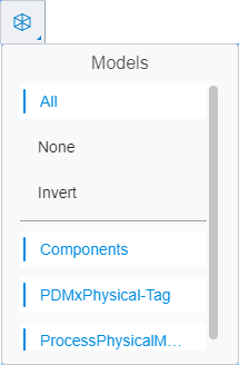
 Categories Categories
|
Used to filter the objects in the model based on
predefined categories. Clicking
expands the
Categories menu. Select the category of
objects you want to display in the view. For instance, select
HVAC to only display HVAC objects.
In addition to the specific engineering discipline
categories, there are some special categories to select.
All can be used to re-display
all the objects in the model.
None clears the display of all objects.
Invert reverses the current selection to
display all other objects besides the selected category.
|
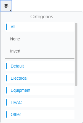
 Views Views
|
Opens
Spacial Views associated with the Digital
Twin. Click
to select a
Spatial View from the pop up menu.
|
 Viewport Viewport
|
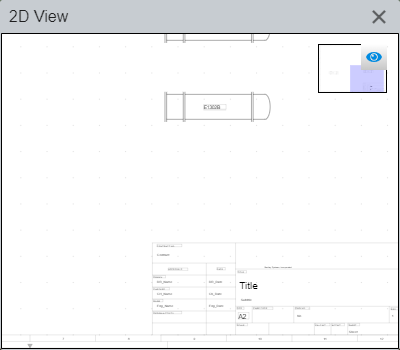
Opens the Viewport window which is used to view
selected objects in a
"2D" view.
|
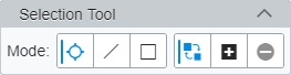
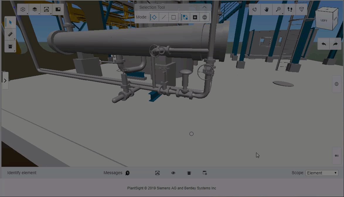
 Select Tool Select Tool
|
Used to select objects in the 3D view. When selected,
objects are highlighted and their properties are displayed in the
Properties list. The
Select Tool's
"mode" is controlled by the
 Selection Tool
Settings. Selection Tool
Settings.
|
| Selection Tool Settings
|
Used to set the
Select
Tool's operation mode. Clicking
opens the
Selection Tool toolbar.
Here, the
Mode settings allow you to select individual
elements or drag to select elements with a dynamic line or rectangle (first
three tools). These work in conjunction with the other
Mode tools that set the objective of the
selection (replace, add or remove) from the existing selection set.
These next
Mode tools work together with the previous
Mode tools to set the objective of the
selection.
| Setting | Description |
|---|
 Replace current selection Replace current selection
|
Clears the current selection set and starts a
new selection set.
|
 Add to selection Add to selection
|
Adds objects to the selection set.
|
 Remove from selection Remove from selection
|
Removes objects from the selection set.
|
Additional
Select tools appear in the view when a
selection is made. These act on the selection set:
| Setting | Description |
|---|
 Clear Selection Clear Selection
|
Deselects all objects in the selection set.
|
 Hide Selected Hide Selected
|
Turns off the display of objects in the
selection set.
|
 Isolate Selected Isolate Selected
|
Turns off the display of objects not in the
selection set.
|
 Emphasize Selected Emphasize Selected
|
Dims the of objects not in the selection set,
leaving the selection set highlighted.
|
|
 Measure Tools Measure Tools
|
Used to measure distances and locations in the
digital twin. Clicking
opens a menu with two measure
tools:
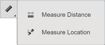
- Measure
Distance - Interactively measures distances between objects
selected in the digital twin, drawing numbered
"trails" with distances in the view. Hover
over or click on to investigate or select objects to measure. When the pointer
is near an object, identifying information is displayed in a flyover. The
pointer can
"snap" to
"keypoints" on the modeled objects
(intersections, endpoints, midpoints) for precise location. Distances are
displayed attached to the pointer as you hover over objects. When you click on
an object, a reference point is established. Clicking on another object again
establishes the second point, and so on for multiple object selections. The
overall distance is always displayed at the last selected object. Ending the
tool (right click) clears the view of the measured distances.
- Measure
Location - Interactively displays model coordinates on numbered
"callouts" in the view. When the pointer is
near an object, identifying information is displayed in a flyover. The pointer
can
"snap" to
"keypoints" on the modeled objects
(intersections, endpoints, midpoints) for precise location. When you click on
objects, numbered callouts are placed. Hovering over them displays the model
coordinates at each location. Ending the tool (right click) clears the view of
the model coordinates.
|
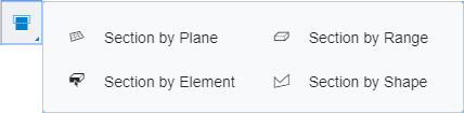
 Section Tools Section Tools
|
Used to create section views of the model via mouse
movements. Clicking
opens a menu with four section
tools:
- Section
by Plane - Creates the cutting plane by hovering the pointer over
an object until part of it is highlighted, and then clicking when the plane
glyph attached to the pointer
 is correctly oriented. is correctly oriented.
- Section
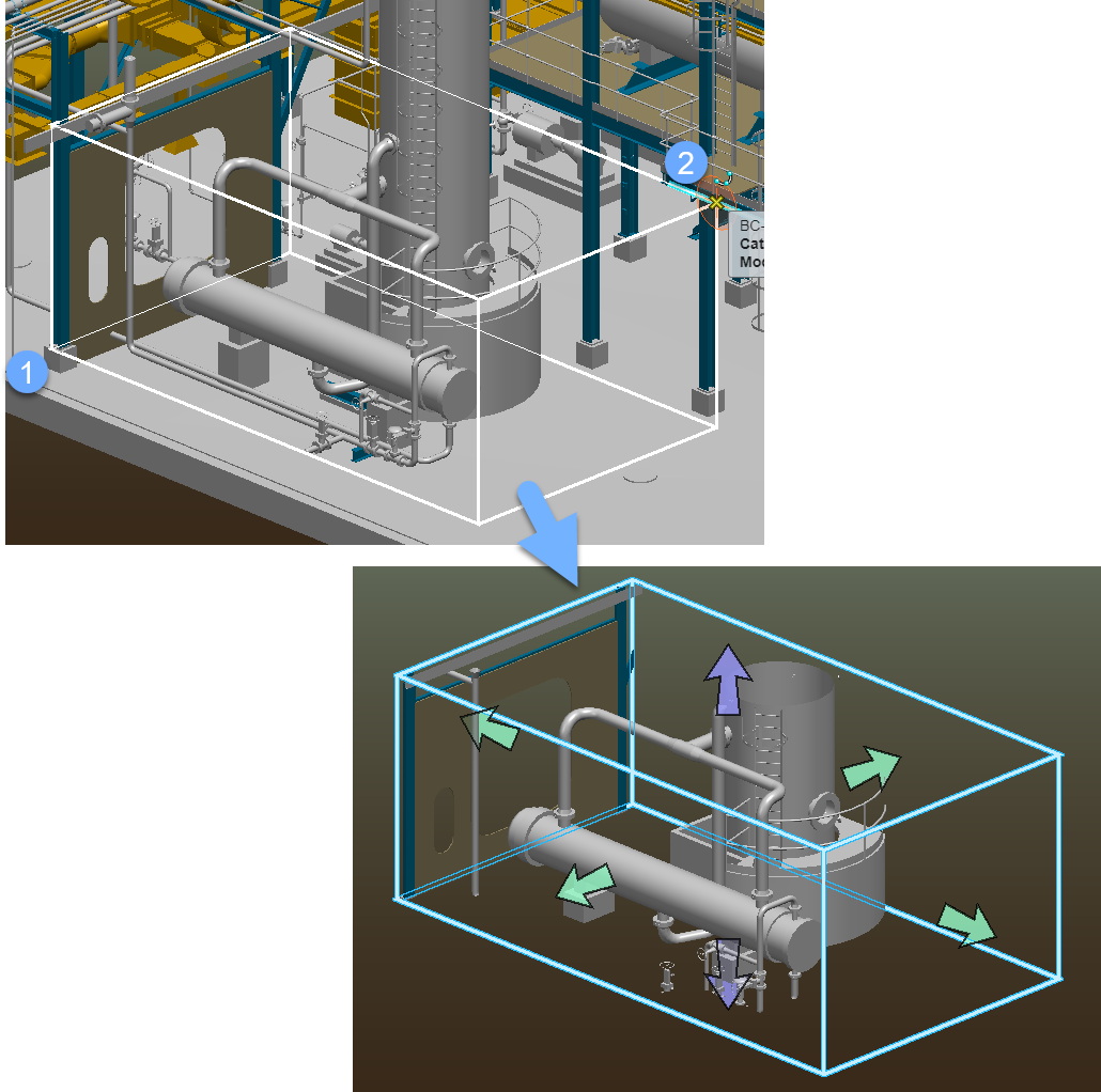
by Range - Creates a range block by selecting two objects in the
model to identify the apposite corners of the block (labeled 1 and 2 below).
- Section
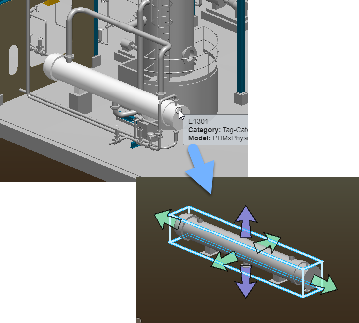
by Element - Creates a range block around an object by selecting
the object. The range block sides can then be dragged outward to create a 3D
section view of the area around the selected object.
- Section
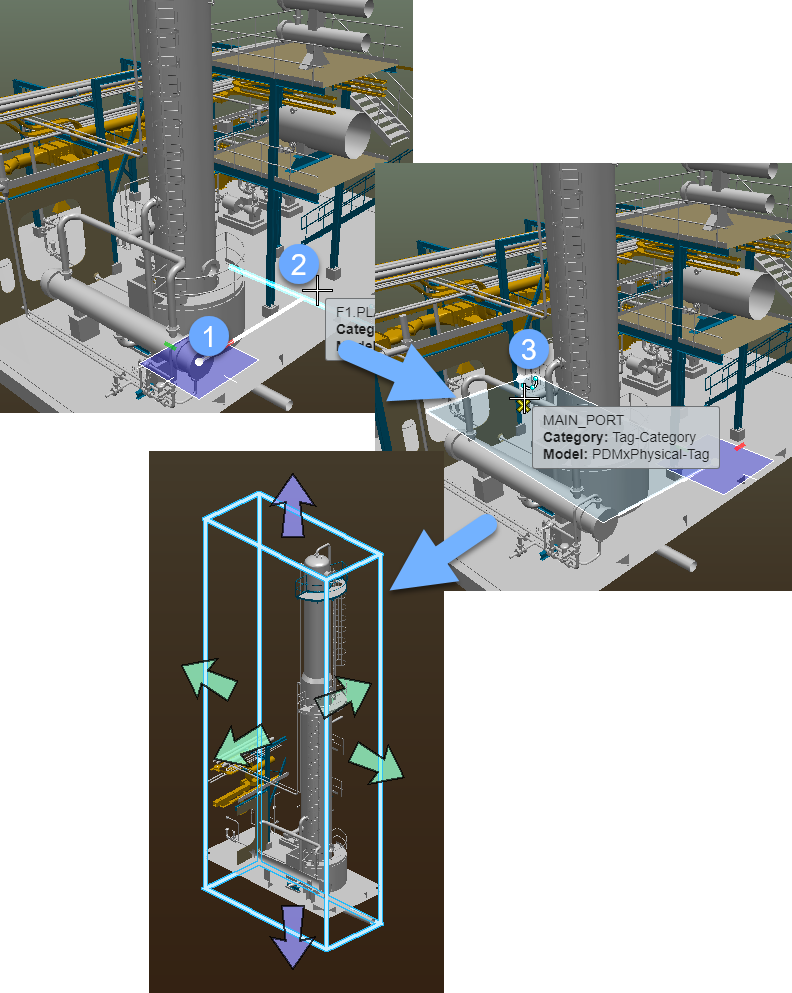
by Shape - Creates a cutting shape by selecting objects in the
model to identify the sides of the rectangular shape (labeled 1, 2 and 3
below). The shape is extruded in both directions (normal to the section shape)
forming a 3D section.
|
 Rotate View Rotate View
|
Used to interactively rotate the view via mouse
movements. Left click and hold while you move the mouse to rotate the view.
|
 Pan View Pan View
|
Used to interactively pan the view via mouse
movements. Left click and hold while you move the mouse to pan the view.
|
 Walk Tool Walk Tool
|
Used to interactively traverse the model via mouse
movements. Left click and hold while you move the mouse. Movements are relative
to the reference points you select by left clicking. Left and right mouse
movements
"walk" you to the left and right, while up and
down mouse movements
"walk" you forwards and backwards respectively.
|
 Zooming tools Zooming tools
|
Used to zoom into the model or fit the model into
the view extents. Clicking
opens a menu with two zoom tools:
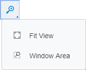
- Fit
View - Adjusts the view magnification so that the entire model is
visible in the view.
- Window
Area - Defines boundaries of a rectangular area of the model to be
displayed within the view.
|
 Toggle Perspective Toggle Perspective
|
Used to turn perspective on or off in the view. In a
view with perspective projection, elements at greater depths appear relatively
smaller, enhancing realism. A view with perspective projection is also referred
to as a camera view.
|
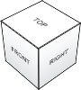 3D Cube 3D Cube
|
Used to rotate the view by clicking on cube faces or
via click, hold and rotate with mouse movements. The cube's faces are labeled
Top,
Front,
Right, etc. Clicking on them orients the
view accordingly.
|
 Undo/Redo View Undo/Redo View
|
- Undo
View - Undoes the last viewing operation (view control operation or
view attribute change).
- Redo
View - Redoes the last undone viewing operation.
|
 Reality Data Reality Data
|
Clicking
or selecting a reality
data object expands the
Reality Data list, and is used to view
object data.
|
 Properties Properties
|
Clicking
or selecting an object expands
the
Properties list, and is used to view object
data.
|
| 3D View toolbar
|
Located at the bottom of the 3D View, is a toolbar
containing view tools, prompts, messages and settings. Several of these tools
work together with the 3D View Selection, Section and View tools.
|
| User prompts
|
Displays instructions for the currently active tool.
Located on the left side of the toolbar.
|
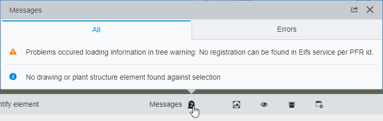
| Messages
|
Displays information, warnings and error messages in
a pop up settings tab that you activate by clicking the
Messages icon in the toolbar.
|
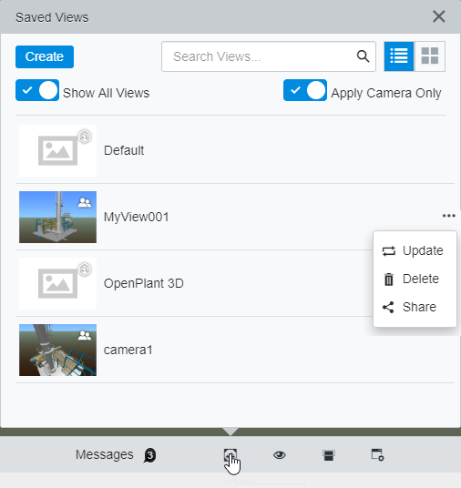
| Saved Views
|
Used to load or to define
Saved Views which are views with specific
settings that you can recall or share with others. Clicking the
Saved Views icon in the toolbar opens the
Saved Views pop up settings tab.
- Create - Used
to create a new saved view. Clicking
Create opens the Create Saved View
dialog where you can enter a
Name for the saved view. Once created,
the new view is listed in the saved views list.
- Search
Views - Allows you to search the saved views by name.
 List view
- Arranges the saved views in a list form. List view
- Arranges the saved views in a list form.
 Thumbnails view -
Arranges the saved views as a gallery of thumbnails. Thumbnails view -
Arranges the saved views as a gallery of thumbnails.
- Show All
Views - When on, all views are listed in Saved Views including
project Views such as the
Default view.
- Apply
Camera Only - When on, only views with the camera on are listed in
Saved Views.
- Saved
Views - Listed in the List view and pre viewed in thumbnail images.
Saved views created by you have an additional menu with more settings (see
above image). Saved views that have a "people" icon in the thumbnail preview
indicate they are shared views.
The following settings are available only for saved
views created by you, and are accessed by clicking the
··· (three dots) button (see above image).
- Update
view - Replaces the saved view with the current view.
- Delete
view - Deletes the saved view including all shared instances.
- Share/Unshare
view - Used to share unshared views, or discontinue sharing shared
views.
|
 Clear Hide/Isolate/Emphasize Clear Hide/Isolate/Emphasize
|
Clears the view, and restores the saved view. Used
when the view is displaying objects that are hidden, isolated or emphasized.
|
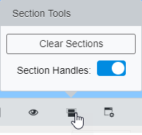
| Section Tools
|
Used to clear or restore section views created with
the
Section Tools. Clicking the
Section Tools icon in the toolbar opens the
Section Tools pop up settings tab.
- Clear
Sections - Clears sections from the view, restoring the full
un-sectioned model.
- Section
Handles - Turns on the display of the section handles so you can
edit the extents of the section view.
Note: A section view
must be defined to enable the Section Tools.
|
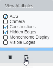
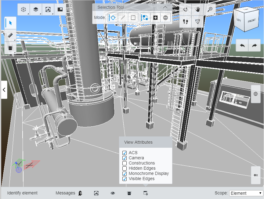
| View Attributes
|
Used to set attributes for the view.
- ACS - When on,
a coordinate triad representing the Auxiliary Coordinate System (ACS) displays.
- Camera - When
on, the view camera is applied to the current view.
- Constructions -
When on, construction elements display.
- Hidden
Edges - When on, hidden edges are displayed with a dashed line
style.
- Monochrome
Display - When on, all objects are displayed in monochrome.
- Visible
Edges - When on, object edges are highlighted.
|
| Scope
|
Sets the
"Selection Scope" which affects how objects are
selected based on their hierarchy in the digital twin.
- Element - When
selecting objects, only the individual objects selected by single selection,
that cross a line, or that fit inside or overlap a range, are selected.
- Assembly - When
selecting objects, the local assemblies of the objects selected by single
selection, that cross a line, or that fit inside or overlap a range, are
selected.
- Top
Assembly - When selecting objects, the top assemblies of the
objects selected by single selection, that cross a line, or that fit inside or
overlap a range, are selected.
The effect of these
Scope settings have on selection are
demonstrated here:
|