This dialog lets you to place a
Grounding Grid in the current drawing.
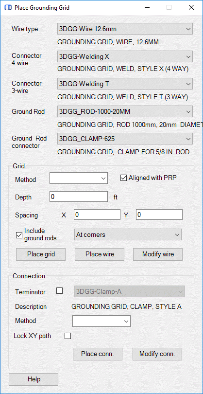
This dialog lets you to place a
Grounding Grid in the current drawing.
Accessed from:
Placing the main grid is done by selecting a part number for the
Grounding Grid wire ( Wire type), plus welding points for 4 wires ( Welding
(X)) and 3 wires ( Welding (T)). The depth of the main grid can be defined
relative the Project Reference Point (PRP) or a Digital Terrain Model (DTM).
Depth is the depth relative the PRP/DTM.
Connections are wires between the main grid and objects
(i.e., structures, fences etc). The connections should first be connected to
the main grid, then to the object.
Objects can contain a Hook Point, which helps terminate the
connection. A clamp can be added to the point where the connection terminates
by enabling the Terminator check-box and selecting the part number for the
clamp (in the corresponding pick-list).
The terminating point for a connection can be located by
selecting
Hook in the Method pick-list. In this case, the
termination point will snap to hook-points. Select Free in the Method pick-list
to position the termination point at any location. If a clamp is placed in
current drawing (and the Terminator option is disabled), select
Symbol from the Method pick-list to force the
termination to locate the symbol placed in the current file and snap to its
origin (i.e., wire clamp).
| Setting | Description |
|---|
| Wire Type
|
Select the type of copper wire you want to place
from the pull-down list. The list is populated with all part numbers that have
a value of GGWire in the Part_Type field of the parts database record.
By default only two types of Grounding Grid wires
are available. However, the user can configure standard cables which normally
placed above ground to be used for grounding grids as well.
|
| Connector 4-Wire (Welding X)
|
Select the type of weld (4 wire point) you want to
use from the pull-down list. The list is populated with all part numbers that
have a value of GGWX in the Part_Type field of the parts database record.
|
| Connector 3-Wire (Welding T)
|
Select the type of weld (3 wire point) you want to
use from the pull-down list. The list is populated with all part numbers that
have a value of GGWT in the Part_Type field of the parts database record.
|
| Ground Rod
|
Determines the type of grounding rod to be placed in
the grid. The option shown in the dialog is the default shipped with
Substation.
|
| Ground Rod connector
|
Determines the type of grounding rod connector to be
placed in the grid. The option shown is the default shipped with Substation.
|
| Grid
|
- Method - Allows you
to place the grid relative to the Project Reference Point (PRP) or the Digital
Terrain Map (DTM).
- Aligned with PRP -
Controls the rotation angle based on the vector defined by the Project
Reference Point. Rotation is counter clock wise (CCW) relative to the Project
Reference Point (i.e., if a value of 10 degrees is entered, the ground grid
will be rotated 10 degrees CCW from the reference vector O. If no Project
Reference Point is placed, the view will be rotated by the absolute value of
the data entry.
- Depth - Allows you
to specify the depth the grid should be placed at relative to the PRP or DTM
depending on which you selected.
- X -Controls the
distance between columns and rows in the main grid (in MicroStation units).
- Y - Controls the
distance between columns and rows in the main grid (in MicroStation units).
|
| Include ground rods
|
When this option is enabled, ground rods will be
automatically placed on the grounding grid using either of the following
options:
- At corners: places
grounding rod at each corner of the grid.
- Each 2nd perimeter
connection: places grounding rod at the four corners plus at every 2nd
connection point around the grid perimeter.
|
| Place grid
|
Places the grid in the current drawing after
selecting two data points (corner-points for the main grid).
|
| Place Wire
|
Adds a wire segment in the main grid.
|
| Modify wire
|
Provides controls for adding vertices to an existing
wire segment.
|
| Connection
|
- Terminator - If
this option is selected, the software will add a user-defined clamp at the
terminating end of the connection wire. Select the type of terminator from the
pull-down list. The list is populated with all part numbers that have a value
of GGClamp in the Part_Type field of the parts database record.
- Method - Allows you
to place the connection by the Hook method which will snap to a hook point on a
substation object or by the Free method which allows you to select any
termination point.
- Lock XY path -
Enable this option to only locate the depth of the break-point (the break-point
will follow the XY path of the existing connection).
|
| Place conn
|
Places a connection between the main grid and an
object.
Note: The
connections should first be connected to the main grid, then to the object.
|
| Modify conn
|
Adds vertices to an existing connection after
selecting the connection wire and adding break-points to the wire.
|
Modifying the Grid
Connector Symbols
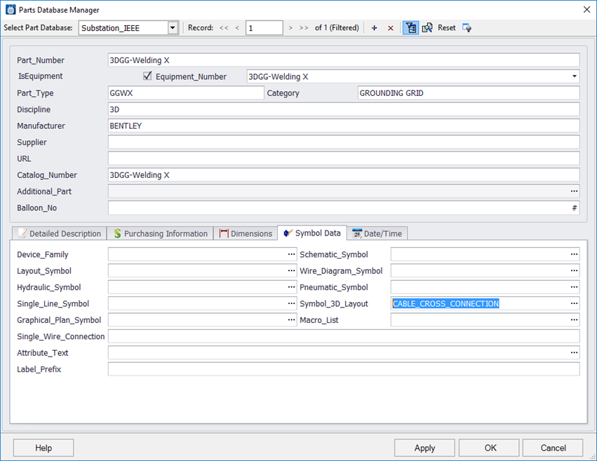
By default, when a grounding grid connector is
placed, the symbol displayed for the connector is a generic dot. You can use
the Part Database Manager to define a specific symbol to insert at the
connecting nodes of the grounding grid if necessary.
Select the Grounding Grid Connector part as shown below,
then set a 3D Layout Symbol value for the connector.
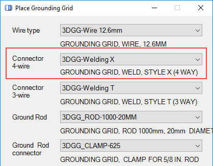
When you go to place a grounding grid, you can call out the part
number in the Place Grounding Grid dialog:
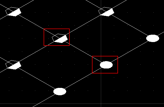
When you place the grid, the connector symbol will display as
follows:
So instead of seeing a plain dot where the cables are joined
together, there is now a special hexagon symbol which was defined for that
part.
You can then create your own legend on the drawing to
define what the different symbols represent.