The Digital Twin Viewer's layout consists of the 3D model
and digital twin data. You can view specific information about the tower, while
selecting objects, and manipulating your view.
Tower Details
Panel
The Digital Twin Viewer includes a tower-specific details
panel located along the left side of the Viewer window, that includes the
following information:
Information
Panel
Located on the right side of the viewer window, this
panel displays context-sensitive tower and component details such as pole and
mount properties, wind load parameters, and other objects, depending on what is
currently selected. For example,
Details
Table
Located across the bottom of the Viewer window. It
displays context-sensitive, searchable information in a table format. For
example,
Status Bar
Located at the bottom of the viewer. displays view tools,
prompts, messages, and settings. Several of these tools work in conjunction
with
Selection,
Section, and
View tools. For example,
For more information, see
Status Bar.
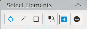
Selection
Tools
In conjunction with the
Select Elements tool (

), you can select the
Selection Tool Settings (

), which displays additional
tools to aid in the selection of objects in the digital twin:
These selection tools allow you to do the following:
| Icon
|
Name
|
Details
|

|
Select Single
|
Selects elements
individually.
|

|
Select by Crossing Line
|
Selects all
objects that intersect with a user-defined line.
|

|
Select by Box Corners
|
Selects all
objects within a user-defined box.
|
After a selection has been made, you can select from these
additional selection tools:
| Icon
|
Name
|
Details
|

|
Replace Current Selection
|
Clears the current
selection set and starts a new selection set.
|

|
Add to Selection
|
Adds selected
objects to the selection set.
|

|
Remove from Selection
|
Removes selected
objects from the selection set.
|
For more information, see
Using
the Select Tool.
 Hide/Show iModel
Toggles iModel visibility.
 3D Cube
Rotates the view by clicking a specific side of the cube
(left, right, front, top, back, bottom, or an edge), to rotate it accordingly,
or alternatively by holding the mouse on the cube and rotating it.
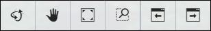
Camera
Tools
| Icon
|
Name
|
Details
|

|
Set Up Walk Camera
|
Lets you define
the area for the camera and walk around.
|

|
Walk Around
|
Interactively
traverses the model via mouse movements. Click and hold while you move the
mouse. Movements are relative to the reference points you select by clicking.
Left and right mouse movements
"walk" you to the left and right, while up
and down mouse movements
"walk" you forwards and backwards
respectively.
|

|
Camera
|
Toggles the view
perspective. When perspective projection is enabled, elements at greater depths
appear relatively smaller, enhancing realism.
|
 Properties Tab
Displays object data by clicking a view icon, or by
select an object to expand its properties. For example,
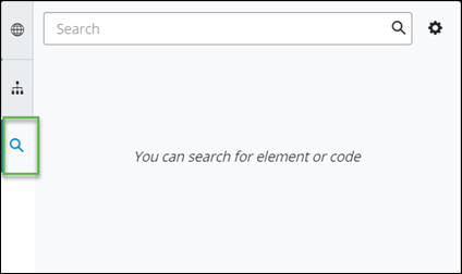
 Search Tab
Performs basic or advanced searches on the digital twin.
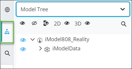
 Visibility Tree Tab
Used
to show or hide elements within the view. Clicking the
Visibility Tree tab expands its controls:
You can select to view by:
- Model
Tree
- Categories
- Spatial
Containment.
 Issues Tools
Displays any issues with the model in the Information
panel.
Options are:
- Toggle Issue
Resolution Panel
- Create
Issue
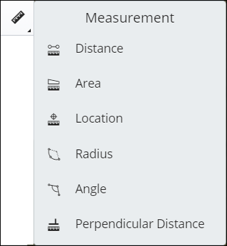
 Measurement Tools
 Version Compare
Lets you compare two different named versions.
 Data Visualization
Lets you customize tower data and equipment by assigning
custom colors to classes and attributes. See
Data
Visualizer.
 Adjust Elevation
This icon is visible when no iModel is present. Clicking
this icon and then selecting the base of the tower adjusts the reality model
elevation.


 Section Tools


