Home Tabs

|
Setting |
Description |
|
Used to lock the active element template when placing an element. When on, the icon is displayed with highlighting. |
|
|
Opens the Element Templates drop-down to set the active element template, and to manage element templates using the Elements Templates dialog. |
|
|
Opens the Level drop-down to set the Active Level and the Active Level Filter, to manage levels and filters, to set the display of levels and apply filters, and to recall existing level filters. |
|
| Color |
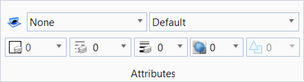
Opens the Active Color drop-down to set the active color, and change the colors of selected elements. |
|
Opens the line style drop-down to set the active line style to the line style that is chosen. |
|
|
Opens the line weight drop-down to set the active line weight and change the line weights of selected elements. |
|
|
Opens the transparency drop-down to set the active element transparency. |
|
|
Opens the priority drop-down to sets the active element priority (2D models only), which determines how an element is displayed relative to other elements. |
|
|
Opens the element class drop-down to set the active class of element on placement. |


Primary

|
Setting |
Description |
|
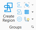
Manage project data using the Explorer dialog. |
|
|
|
|
Models |
Displays the Models dialog, which allows you to create a new model, copy a model, edit model properties, delete and import models, create a sheet boundary, and list any filters. |
|
Turn levels on and off using the Level Display dialog. |
|
|
Turn levels on and off using the Level Display dialog. |
|
|
Review or modify information about an element(s), such as its type, attributes, and geometry. |
|
|


Selection
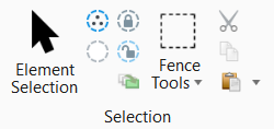
The Selection group is used to select and deselect elements for modification or manipulation.
|
Setting |
Description |
|
Element Selection |
Select and deselect elements on a per element basis, by defining an area, or by drawing a line that intersects them. |
|
Select All |
Select all elements in the design. |
|
Select None |
Deselect all elements in the design. |
|
Lock |
Locks selected elements. The attributes and location of a locked element cannot be changed. |
|
Unlock |
Unlocks selected locked elements. |
|
Bring to Front |
Brings the selected elements to the front of the view display. |
|
Fence Tools |
|
|
Cut |
Used to cut selected elements to the clipboard. |
|
Copy |
Used to copy selected elements to the clipboard. |
|
Paste |
Used to paste elements from the clipboard. |


Placement


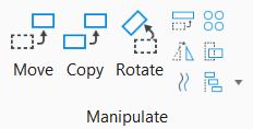
Manipulate
| Setting | Description |
|---|---|
|
Move |
Move an element(s). |
|
Copy |
Copy an element(s). |
|
Rotate |
Rotate an element(s). |
|
Scale |
Resize an element(s) by the active scale factors. |
|
Mirror |
Mirror an element(s). |
|
Move Parallel |
Move or copy an element with the sides of the copy parallel to the original. |
|
Array |
Copy an element(s) many times to create a rectangular or a polar (circular) array. |
|
Stretch |
Stretch an element(s). |
|
More |


Modify
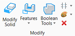
|
Setting |
Description |
|
Used to manipulate faces, edges or vertices of a solid by pushing or pulling them interactively |
|
|
Used to select and manage features used in creating a solid. |
|
|
Boolean Features toolbox contains tools to construct parametric solids by uniting, intersecting, or subtracting existing solids. |
|
|
Used for creating and modifying 2D tools. |
|
|
Used to change selected attributes of an element(s). Change Element Attributes tool settings are used to specify the new attribute settings. |
|
|
Used to delete an element(s) from the design. |