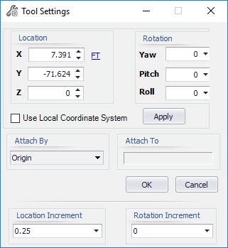
Component Placement Dialog
The following dialog is displayed when either of the following commands are executed:
- Place a new component using the Free Placement method.
- Use the Model Operations Component Manipulator to reposition an existing component.
| Setting | Description |
|---|---|
| Location | Define the distance by either typing in the value directly, or using the arrow buttons to adjust the distance incrementally. Click on the units option to the right of the distance field to display a drop down list of available units to choose from. The Lock icon locks the current distance allowing you to possibly rotate the component, or adjust other fields while still keeping the same location. You can unlock the distance field and continue to adjust the distance until the final placement location is accepted. |
| Relative To | Allows you to change the origin point using one of the following
options:
|
| Use Local Coordinate System | When placing a free standing component, the component's location is placed in reference to the Global Coordinate System (which usually is set to 0,0,0). Once you select the initial placement point, you can use this option to adjust the component's position relative to the original placement point. When using the Component Manipulator command to move a component, you can enable this option to use the original placement point as the reference point defining the new location. In either instance, you must enable the option then click Apply to use the Local Coordinate System. |
| Attach By | Provides a list of connect points for the support being placed.
As you select a point from the list, the connect point will change dynamically
in the model so you can visualize how the support will be placed.
This options is particularly useful when placing support steel and using the offset options where you can offset the pipe from either the center of the support frame on T's and U-Frames, or from the end of the horizontal beam on an L-Frame support. Refer to the Support Frames section for additional information on this. |
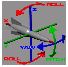
| Rotation | These fields allow you to determine the rotation degrees for the Yaw, Pitch, and/or Roll. When you hover the mouse over the Rotation header, the following images displays the rotation direction of each of the three fields. Enter a rotation in degrees in the field or select one of the following options from the drop down menu. |
| Location Increment | Determines the increment value used when clicking the arrow icons to adjust the Distance. |
| Rotation Increment | Determines the increment value in degrees for the rotation sliding scale. For example, if you select 15 degrees from the drop down list, when you use the Rotation sliding scale, the component will rotate in 15 degree increments. |
| Apply | When whatever settings have been defined in the dialog while still keeping the dialog open in case additional changes are needed. |
| OK | Click to apply the changes and close the dialog. |
| Cancel | Closes the dialog and cancels the command. |