Valves Gallery
Displays a variety of pre-defined valve symbols which can be placed on a Pipe Run.
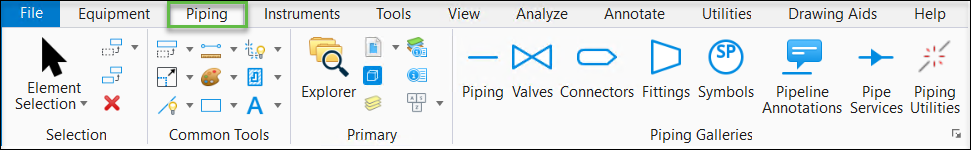
Accessed from:
The following gallery displays which can be left floating or docked to the drawing area.
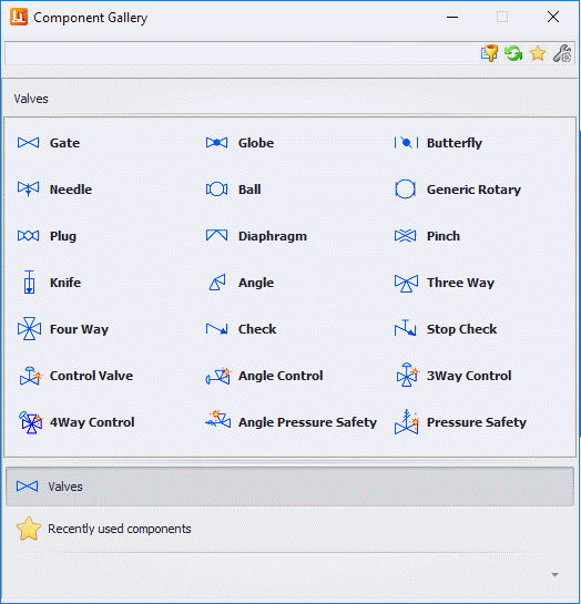
After the valve symbol is selected, you are prompted to select the Pipeline or Pipe Run to place the valve. If more than one valve exists in the specification you are using, then the Records dialog displays prompting you to select which valve to place.
The Component Properties dialog then displays prompting you to define a tag number for the valve and make any changes to the valve's component properties. When finished define properties for the valve click OK to close the dialog and complete the placement process.
| Setting | Description |
|---|---|
| Check Valves | Check Valve symbols will inherit the flow direction from the Pipeline or Pipe Run on which they are placed. The Component Properties dialog displays prompting for a tag number before placement. |
| General Valves | General Valve symbols are placed using a fixed scale size and will inherit the properties of the line they are placed on. The Component Properties dialog displays prompting for a tag number before placement. |
| Control Valves | Control Valves are valves with actuator symbols attached to the valve body. A control valve is built "on-the-fly" by selecting a specific valve body and actuator from the Place Control Valve dialog. Additional information on these valves are found by click the link within this section or below. |
| Pressure Safety Valves | The Valves gallery also includes both inline and angle Pressure Safety Valves symbols which can be placed on the current drawing. Additional information on these valves are found by clicking the link within this section or from the provided links below. |