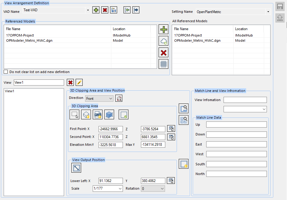
View Definition
 Displays options to define
settings for a VAD (View Arrangement Definition) file.
Displays options to define
settings for a VAD (View Arrangement Definition) file.
Accessed from the Command Options panel.
Create View
A drawing view is a 2 dimensional rectangular shape in the drawing, which contains the graphics of 3D model files. The view has referenced models that may have either one or more than one of the 3D piping models, equipment models, structure models or others.
There may be more than one view in the drawing and all the geometry data in 3D models should be clipped by the view plane.
They should be transformed from the 3D model to the drawing according to their view information respectively. The view information has referenced model specifications, the position, view scale and view rotation.
| Setting | Description |
|---|---|
| VAD Name | Displays the available VAD files in a drop down list. Select one to display its settings. A list of demo files are included with the install. |
New VAD File

|
Displays the Specify VAD File Name dialog where you can name a new VAD file to be defined. Once created it will become the active VAD file. |
Delete VAD File

|
Deletes the VAD file active in the View Definition area. You will be prompted to confirm the intent to delete the file. |
Save VAD As

|
Displays the Save VAD As dialog where you can save the existing VAD file under a different file name. |
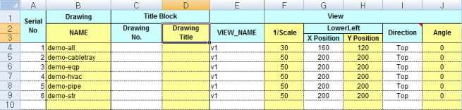
Import VAD File

|
Lets you import an existing Excel file containing VAD data. You are prompted with the Open dialog where you can select the Excel file to open. To view the format of the Excel spreadsheet, you can open a sample file from the following location: |
Export data to Excel Sheet

|
Displays the Output Excel File dialog where you can save existing VAD files to an Excel file. |
| Setting Name | Select the setting name from the drop down list to apply to the view. |
| Referenced Models | This section lists the models which are referenced to create the current view. |
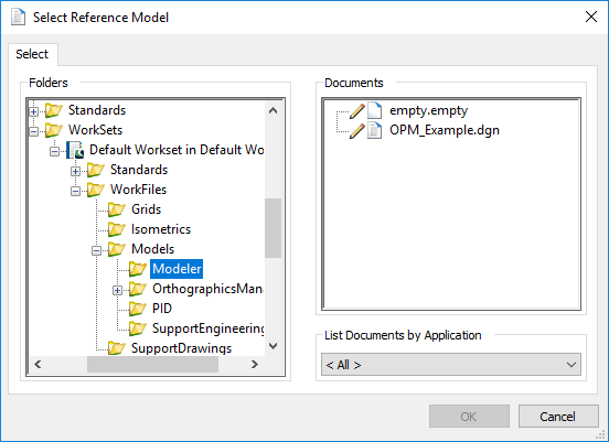
Add a Reference Model

|
Click the icon next to the Referenced Models grid to
display the following options to attach a reference file:
|
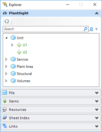
Add/Open a Connected Model
|
This lets you add models/components from PlantSight. This option is only enabled when the selected WorkSet is associated to a CONNECT Project and has been provisioned. This option will automatically login to PlantSight and opens the Platform interface where you can reference out components using the Explorer dialog. |
Delete a Referenced Model

|
Click the icon to remove referenced models(s) from the list and click the icon to remove it. |
Structural Column Grid

|
Offers two options to Add/Edit Column Grids to the
view.
|
| Do not clear list on add new view |
When this option is enabled, the referenced models listed will remain when you click Save to save the settings for the current view. Otherwise the referenced models will be cleared along with the other view settings. When creating several views using the same referenced models, this will prevent you from having to add the models for each view. |
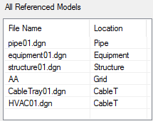
| All Referenced Models | This section displays all of the models that are referenced between all of the view defined in the current VAD file. |
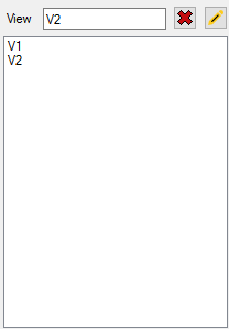
Views Section
This section lists all of the View Names defined for the current VAD file. The following option are available for this section.

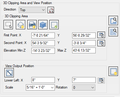
3D Clipping Area and View Position
In this tab, you will define the clip information/coordinates for the current view to be included in the VAD file as well as define how the view will display in the 2D drawing including Lower Left position, Scale and Rotation.
| Setting | Description |
|---|---|
| Direction | |
View a Referenced Model

|
Click the icon to load the referenced model(s) in the CAD module so you can define the clip information. The referenced model(s) will be loaded in the view specified from the Direction list. |
| Position |
The clip plane is defined by input X,Y information from two points, which define two opposite corners of a rectangular box. The Elevation coordinates help to round out the volume of the clipping area. The First and Second points may be defined one of three ways: Direct Entry: Enter the coordinates directly into the fields provided.
Pick first point
Pick Area
|
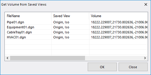
Get Volume from Saved Files

|
Click the icon to load Get Volume From Saved Files defined in MicroStation and stored in the dgn file. This displays the following dialog listing all of the available views stored in dgn. |
Load RWA

|
Click the icon to load volume defined in the RWA (Rebis Work Area). |
Get Reference Model Range

|
Click to automatically get the range of the referenced model. |
Check Area

|
Click this icon to display the clipping area box in the CAD module. |
| View Output Position | |
| Get Position and Scale | Click to set the view position. Once you have used
the Get Referenced Model Range option to get the range of the referenced models
and loaded the drawings, this option will automatically set the location and
scale for the new view.
When creating a second view within the VAD, if you click this option to get the position and scale you will be prompted to rearrange for multiple views. This will automatically set your output for 2 views. |
| Lower Left Position |
In the fields provided, input the X,Y coordinates which will indicate where the lower left corner of the defined view will be placed in the 2D drawing. You can also pick the lower left position in the 2D drawing if you have the border drawing open. (The best way to do this is to click the Borders options page and click the View Border icon.) Once the border file is loaded, click the Position
Locate
|
| Scale |
Select a scale for the view from the drop down list. This scale determines how much the model is reduced when the output drawing is generated. For example, if the scale is set to 1/4" = 1'-0" as shown above, then a distance that measures 40' in the model would be scaled down to measure 10" actual size in the 2D drawing. |
| Rotation | Select a Rotation angle from the list (0, 90, 180, 270), if you wish to rotate the view in the 2D drawing. |
Load Updated View Position

|
Click to update the view definition. |
Display Views
|
Click to view the arrangements up to this point in the CAD module. |
View Border

|
Will open the border file in the CAD module. |
 : Click the icon to pick the
location of the first point in the model. Once you pick the point, the
coordinates will display in the First Point fields. You can repeat the process
for the Second Point fields to create the clip box.
: Click the icon to pick the
location of the first point in the model. Once you pick the point, the
coordinates will display in the First Point fields. You can repeat the process
for the Second Point fields to create the clip box.
 : Allows you to manually pick the
first and second points. Once you have selected both points, the coordinates
will display in the First and Second Point coordinate fields.
: Allows you to manually pick the
first and second points. Once you have selected both points, the coordinates
will display in the First and Second Point coordinate fields.
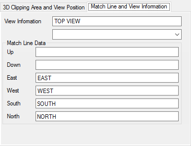
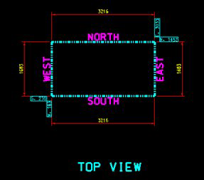
Match Line and View Information
In the Match Line and View Information, enter the information you want displayed on the 2D output drawing in the fields provided. The settings for the Match Line data and View Information are defined in the Outside > View Annotations options page.
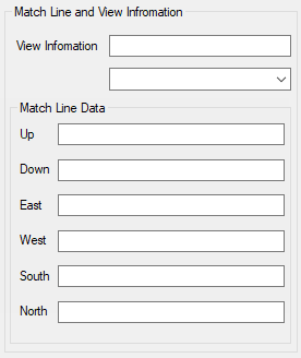
For example, for a Top View with a Rotation of 0 deg, the following values will appear as follows: