Duct Bank Router
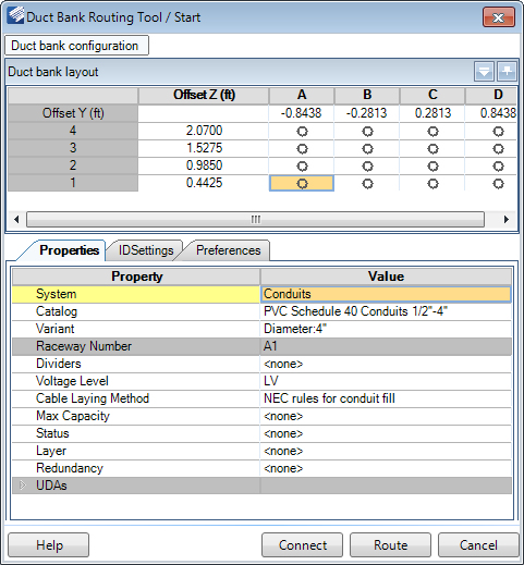
The Duct Bank Router enables you to interactively route duct bank in your current design file. The Duct Bank Router uses the following Start dialog allowing you to configure the properties of the duct bank before routing in the model.
Duct Bank Configuration
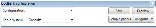
Click the Duct Bank configuration icon at the top of the dialog to display the following drop down with options to define the Configuration and Cable system:
| Setting | Description |
|---|---|
| Configuration | The Configuration field will list saved configurations if any exist, which can be loaded and used/modified. It also allows you to type in the name for a new configuration and save it for future use. |
| Cable System | The Cable system field lists the active system as defined in the System field in the Properties section of the Routing Tool. When routing duct bank, Conduits are the only Cable System that will apply. |
| Setup Spacers Configuration | Spacers are used in the duct bank to define the size and distance between conduit in the duct bank being routed. Click the icon to display the Spacer Configuration Tool allowing you to define the layout and properties for the spacers. |
| Set Conduit Layout Only | Display the Setup Grid dialog allowing you to define the number of conduit slots to include in the duct bank. |
| Save | Saves the current configuration setup. |
| Preview | Displays a preview of duct bank arrangement as shown below: |
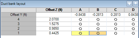
Duct Bank Layout
The Duct Bank Layout section display the Duct Bank configuration as it was defined in the section above and allows you to define the Property/Preference values for the conduit which will be run through the duct bank.
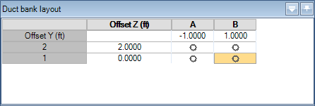
Click in a grid cell and use the Properties section to define the conduit properties. Each cell can contain different size conduit components with unique property values. You can also copy a component from one cell and paste it into others, which will copy the property values as well.
The Offset values define the spacing between the conduit components and the value is typed directly into the field.
Duct Bank Properties
| Setting | Description |
|---|---|
| System | Select the type of system to run for the duct bank. Note that Conduits is the only system available for selection. |
| Catalog | Select a catalog to use from the drop down list. The Cooper catalog is included with the install and has predefined sizes of Conduit to select from. |
| Variant | Define the size of the conduit to be included in the duct bank. |
| Raceway Number | This number corresponds with the column and row of the Duct Band layout. For example Column A, Row 1 would have a Raceway Number of A1. |
| Dividers | If the raceway is to be divided into different sections, define a number of dividers to use here. |
| Divider/Section [%] (OPTIONAL) | If the raceway contains dividers, then these fields display letting you define the percentage of space each divided section will occupy. The number of fields which display is determined by the amount of sections the raceway is divided into. |
| Voltage Level | Select a voltage level from the drop down list: |
| Cable Laying Method | Select the method of laying the cable from the following list of options. This determines the routing configuration for the cable inside the raceway/conduit. |
| Max Capacity | The Max Capacity determines the maximum percentage of the raceway/conduit which can be occupied by cables. |
| Status | Define the status for the duct bank from the following list: |
| Layer | Select which layer the duct bank will be modeled on from the drop down list. By default, duct bank is placed on a specific layer as defined in the CAD Standards > Levels page of the Options dialog. |
| Redundancy | This field will assign a label to redundancy runs which may be required. The default labels to select from are: Additional label values can be defined in the Raceway > Specifications page of the Options dialog. |
| Accessories (Route) | Select a channel size for the duct bank from the drop down list. |
| Accessories (Raceway) | Select raceway accessories (dividers, brackets, covers etc.) to be included in the duct bank from the drop down list. |
ID Settings
| Setting | Description |
|---|---|
| Save | The Save option can be used to save and reuse any commonly used macros and share them with all project participants. All ID Settings configurations are stored in the metadata folder in the CFG_RacewayLabels.xml file. |
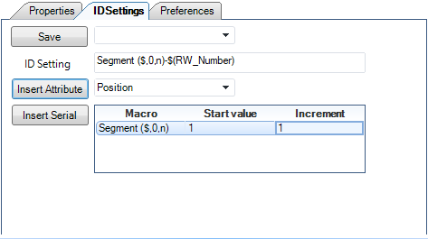
| Insert Attribute | This section lets you add one or more attributes to
the Duct bank ID. You can use special characters as separators between
attributes such as (-) shown above.
To include the Raceway Number (Position) in the
ID, add the
Position attribute as shown in the image
above. The Raceway Number corresponds to the column and row position in the
layout grid.
For example if only the following cells are selected, Then the ID string will display as follows in the drawing: |
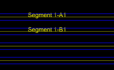
| Insert Serial | By default the Insert Serial option will insert the
segment number as the default ID. You can use the Insert Attributes option to
add additional attributes to the ID if desired. After the raceway layout is
placed, it is automatically adjusted to the first available number. User can
manually overwrite the start value.
By using a macro ($,0,n), the serial number (Segment number) will be generated taking into account the start value and increment. |