Modify Component Dialog
When modifying a piping component in OpenPlant Modeler , the following dialog displays allowing you to modify the properties for the component. These are the same property fields that are defined when the component is placed. For components with Tag Information, such as valves, this information can be modified with this dialog as well.
Accessed from: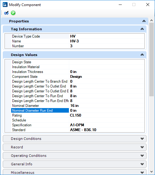


Properties Tab
This section displays a variety of property tabs which expand displaying editable fields to define the property values of the component. An example is shown below:| Setting | Description |
|---|---|
| Component Name | Enter the tag number for the component. |
| Operating Conditions | Represent real life conditions that a component will most likely be exposed to. |
| Design Conditions | Specific working conditions the component class was intended to operate in. |
| Model Server Info | Enter Design State for the component. |
| General Info | Properties defining general physical properties of the component being placed. |
| Miscellaneous | Miscellaneous properties pertaining to the component. |
Tag Browser (Available only when OPPID i-model is referenced)
If you have a OpenPlant PID i-model attached as a reference, you are able to access the tags from the OPPID drawing and use them when placing 3D components. When you select a piping component for placement, the following Tag Browser section is displayed at the top of the Place Component dialog:
The Reset button will reset the tag number to its original value.
Detail Sketches
The Detail_Sketch property has been added to the OpenPlant3D schema at the DEVICE level, meaning you can define a detail sketch for a specific component to be included when generating an isometric using the OpenPlant Isometric Manager. This property can be defined when initially placing the component, or when modifying one. It is located in the Miscellaneous tabbed section as shown below: Enter the name of the detail sketch cell into the field to include it when generating an isometric.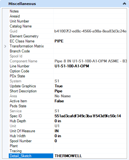
By default, the OpenPlant Isometrics Manager will look to the default cell libraries which are included with install, one of which is named Detail_Sketch.cel. The cell libraries are located in the Cell directory for each isometric style in the project. For example, the IFC style can be found in the following directory:
...\OPModeler_Imperial\Standards\Isometrics\Styles\IFC\Cell\If you define a detail sketch cell file in the Detail_Sketch property field, that cell must be included in one of the cell libraries or the isometric process will not find it causing an error. If you have existing detail sketches defined in a cell library, you can copy that file into the Cell directory for the isometric style and the Isometrics Manager will find it.
Click Here for a detailed procedure on how to add a detail sketch to a cell library and include it on an isometric.